Presentation and typical examples
Presentation
The Flux PEEC software (Inductance Calculation) is a numerical tool for the computation of parameters characterizing the parasitic couplings within complex structures in Electrical Engineering and/or Power Electronics.
It allows the evaluation of the electric circuit parameters (R, L, M) associated to the conductors of more or less complex geometry, placed in the air.
* This method is in the quasi-stationary approximation; the capacitive effect is neglected.
Current applications
The most current applications of Flux PEEC are related to the design of electric connections between components of different structures, such as:
- electrical power supply
- bus bars in power electronics
- power modules of electric converters
- electrical connections
Computation with Flux PEEC
Flux PEEC proposes a harmonic calculation (for various frequencies) of the electric connections. Two types of computation* are proposed; which provides the user with two complementary approaches of the structure to model.
* In the software, these two modes of calculation correspond to two applications (called Supplied conductors, and Conductors impedance).
Application “Supplied conductors”
In the first type of computation, known as “ Supplied conductors ”, the user analyzes the structure in its electric environment, i.e. including the supply circuit (current or voltage supply sources and passive electric components of resistance, inductance or capacitance type).
The main result is the electric current flowing in the conductors.
Starting from the current, other electromagnetic quantities can be computed such as:
- the magnetic flux density B in the area surrounding the conductors
- the electrodynamic force between conductors (Laplace force)
- the power losses in conductors (losses by Joule effect)
Application “Conductors impedance”
In the second type of computation, known as “Conductors impedance”, the user deduces some equivalent parameters of the studied structure from the PEEC computation. These values are then used as input data for an electric circuits simulation software, such as SPICE, SABER, MODELICA, PORTUNUS,…
The main result is the impedance of portions of the circuit defined by the user.
Possibilities
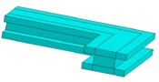
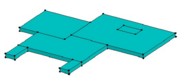
It is possible to model with Flux PEEC two types of conductors: the uni- and bidirectional conductors as presented in the table below.
| An unidirectional conductor is a … | |
|---|---|
Note that the path of 1D conductor can contain bends and the changes in direction are not necessarily of right angle. |
|
| A bidirectional conductor is a … | |
|---|---|
|
|
Limitations
The limitations are the following:
- the conductors are uni- or bidirectional
(Tridirectional conductors cannot be taken into consideration)
- for 1D conductors, the size and shape of the cross-section must remain constant throughout each conductor portion between two bends
- the cross-section of 1D conductors and the shape of 2D conductors must be defined as a sequence of segments, that is to say that the parts in arc of a circle or ellipsis are forbidden
- only the 1D conductors of tube type and whose section is:
- either rectangular
- or irregular and hollow
can be composed of a material with magnetic properties.
For more details on these definitions, the user can refer to § General approach; tube conductor and assimilation conductor.
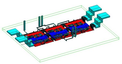
Example 1
Study of a power module made up of three diodes and three IGBTs in parallel (MGE UPS Systems).
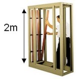
Example 2
 |
 |
 |