Representation of graphic symbols
Introduction
This section is about the location of the graphic symbols of the electric components (resistors, inductors, capacitors, voltage sources, current sources and impedance probes) in the graphical zone.
The user who has chosen to display the graphic symbol of a component has to define its location by means of one of the following options:
- automatic location
- location with terminal and ratio
- location by pins coordinates
- location with terminals
The setting of these options is detailed in the following sections.
Automatic location
The location of the component is set automatically by Flux PEEC which places the graphic symbol in order to have the least possible number of conflicts/interferences with the geometry.
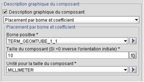
Location with terminal and ratio
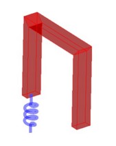
This option places the positive terminal of the component with respect to another already existing terminal (from a conductor or another component). The orientation of the graphic symbol is set automatically by Flux PEEC whereas the size of the component is defined by the user.
If the user chooses this location option, he has to:
- select the terminal (of a conductor or another component) with respect to which the positive terminal of the component will be placed
- define the size of the symbol as well as the unit; a negative value for the size means an inversion of the graphical orientation of the symbol
The Flux PEEC window used for the definition and an example of this kind of location option are displayed below:
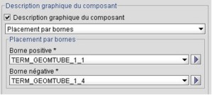
Location with terminals
With this location option, both terminals (positive and negative) of the component symbol are placed with respect to another already existing terminal (of a conductor or another component). The orientation and the size of the graphical symbol are fitted automatically by Flux PEEC.
If the user chooses this location option, he has to:
- select the terminal (of a conductor or of another component) with respect to which the positive terminal of the component will be placed
- select the terminal (of a conductor or of another component) with respect to which the negative terminal of the component will be placed
The Flux PEEC window used for the definition and an example of this kind of location option are displayed below:

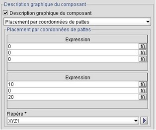
Location with pins coordinates
With this location option, both terminals (positive and negative) of the component symbol are placed by means of a coordinates system and the X, Y and Z coordinates of the points. The orientation and the size of the graphical symbol are fitted automatically by Flux PEEC.
If the user chooses this location option, he has to:
- define the coordinates of the point where the positive terminal of the component will be placed
- define the coordinates of the point where the positive terminal of the component will be placed
- select the coordinates system to which the points coordinates refer
The Flux PEEC window used for the definition of this kind of location option is displayed below: