BasicFEA

Points panel

Points panel

Previous topic Next topic Expand/collapse all hidden text  

Points panel

Previous topic Next topic JavaScript is required for expanding text JavaScript is required for the print function  

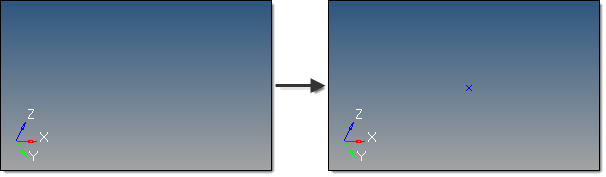
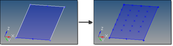
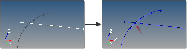
Use the Points panel to create free points using a wide variety of methods.

The following subpanels create points using specific methods. Each is accessed from a toolbar-like strip of buttons on the Points panel.

pointXYZ-24 pointArcCenter-24 pointExtractParametric-24 pointIntersect-24

Note:This toolbar is docked inside the panel and cannot be undocked, moved or hidden.


Subpanels and Inputs


The Points panel contains the following subpanels and command buttons:

pointXYZ-24

Use the xyz subpanel to create free points by specifying (x,y,z) coordinates.

This subpanel creates free points by specifying (x,y,z) coordinates.

pointspanel_xyz_example

A new point is created with x=5, y=5, and z=5, relative to the global coordinate system.

There are several methods for entering the coordinate values:

Type the coordinate values manually into the input boxes.
Populate individual coordinate values using the x, y and z collectors and selecting a node graphically.

When using each of these collectors, the respective x, y, or z coordinate value is copied from the selected node into the corresponding input box.

Populate the coordinate and system values using the as node collector and selecting a node graphically.

This will copy the respective x, y and z coordinate values and the reference system value from the selected node into the corresponding input boxes.


By default, free points are created relative to the global system; however, a local coordinate system can be specified using the system collector. This system can be rectangular, cylindrical or spherical.  However, unlike nodes, free points cannot be assigned a reference system and are therefore not updated to reflect any subsequent changes made to the system.


pointArcCenter-24

Use the Arc Center subpanel to create at the center of the arc that best approximates the input set of nodes, points or lines.

This subpanel creates free points at the center of the arc that best approximates the input set of nodes, points or lines.

pointspanel_arccenter_nodesexample

Here, three nodes selected produce a point at the center of the arc that they form.  Three input points would work similarly.

pointspanel_arccenter_linesexample

Here, two selected lines are used to determine the arc center.  Note that the curved line could also have been used alone.

For nodes and points input, a minimum of three must be selected.

For lines input, the selection must not all lie on a straight line.

An optional tolerance is available to verify whether the calculated best fit circle is sufficient.  If ignored, the best fit circle is always calculated.  Otherwise, an error is returned if the input entities are not all on the circle within the specified tolerance.


pointExtractParametric-24

Use the Extract Parametric subpanel to create free points at parametric locations on lines and surfaces.

This subpanel creates free points at parametric locations on lines and surfaces.

For lines:

0.0 <= u lower bound <= u upper bound <= 1.0.
If the lower and upper bounds are the same, only one node is created.
If the number of u nodes is specified as 1, only the lower bound is used.
The line parameterization type can be specified as either arc length or internal.

pointspanel_extractparametric_example

This example shows u ranging from 0 to 1, with six u points, created evenly along the arc length.

For surfaces:

0.0 <= u lower bound <= u upper bound <= 1.0.
0.0 <= v lower bound <= v upper bound <= 1.0.
The number of u and v free points must be >= 1.
The total number of free points created equals (number of u points * number of v points).
The surface parametric area is scaled to the visible surface area. Free points will be created inside the visible surface area.

pointspanel_extractparametric_surfexample

This examples uses u from 0 to 0.75 with 4 u points, and v from 0.25 to 1.0 with 6 v points.


pointIntersect-24

Use the Intersect subpanel to create free points at the intersection of geometric entities: lines/lines, lines/surfaces, lines/solids, lines/planes, vector/lines, vector/surfaces, vector/solids and vector/plane.

This subpanel creates free points at the intersection of geometric entities: lines/lines, lines/surfaces, lines/solids, lines/planes, vector/lines, vector/surfaces, vector/solids and vector/plane.

A free point is created at each intersection location.

pointspanel_intersect_example

Though difficult to see in the second image, a new point was created from the selected lines.

For surface, solid and plane intersections, if the input line or vector lies on the surface/solid/plane the result is undefined and unpredictable.

For vectors, the magnitude and direction of the vector do not have any effect on the result.  The vector extends through the entire model space.


See Also:

Alphabetical List of Panels