Composite Stress Toolbox
Composite stress toolbox functionality.
Composite stress toolbox functionality is provided in the Composite Browser. Engineering constants, load response, first ply failure, and strength analyses are included. All analyses are accessible via the Analysis entity driven workflow. Engineering constants are additionally accessible via the right-click context menu of relevant entities.
Engineering Constants
- Materials
- Plies
- Zones
- Laminates
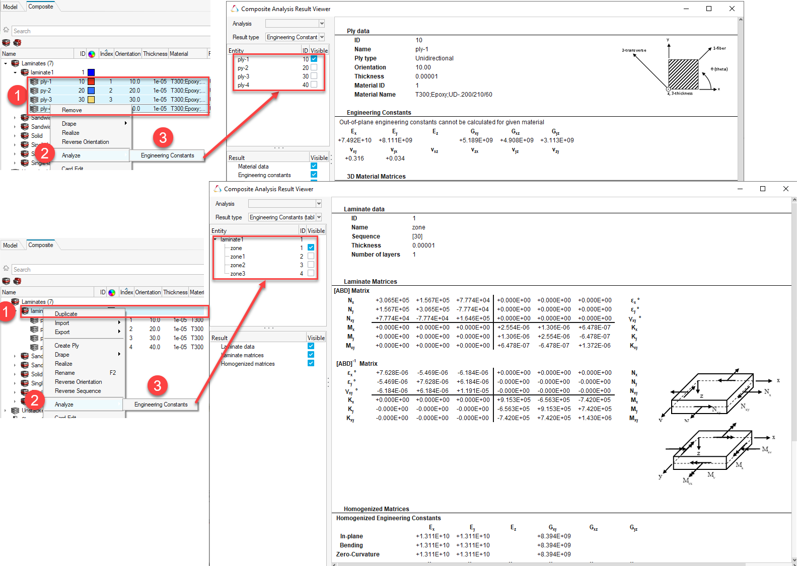
Figure 1.
- Selection of multiple entities of the same type is also supported and generates a list in the Composite Analysis Result Viewer, from which desired results can be selected.
- Only one analysis entity can be selected and run at a given time. All analyses’ results can be accessed via the Analysis combobox in the Composite Analysis Result Viewer.
- Material data
- Engineering constants
- 2D/3D material matrices
Calculations are output in the material system. Note that 3D properties can only be calculated for materials which provide the necessary data (for example, OptiStruct MAT9OR).
- Ply data
- Engineering constants
- 2D/3D material matrices
Calculations are output in the laminate’s material reference orientation. Accordingly, the ply angle entered in the ply Orientation field is used to transform the properties from ply fiber direction to the laminate material reference orientation. For more information, refer to Fiber Orientation.
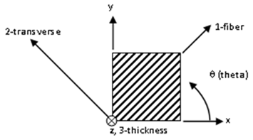
Figure 2.
- Laminate data
- Stiffness and compliance matrices
- Homogenized engineering constants
- Normalized homogenized matrices
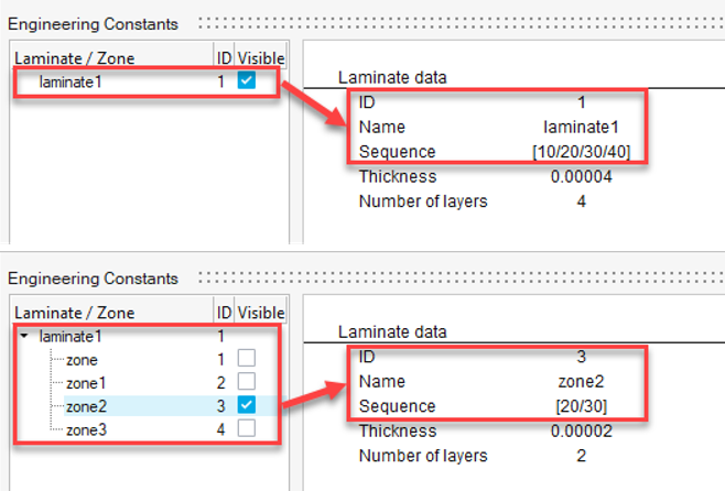
Figure 3.
- Laminate data
- Stiffness and compliance matrices
- Homogenized engineering constants
- Normalized homogenized matrices
Additionally, stacking sequence, thickness and number of layers are summarized for each zone.
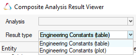
Figure 4.
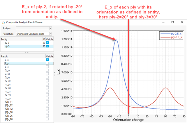
Figure 5.
Engineering constants calculations are also available through the analysis entity driven workflow as outline in the following for other analysis types.
Load Response/Failure
The response of a laminate due to an applied load is calculated based on its behavior derived from Classical Laminate Theory. For transverse shear, First Order Shear Deformation Theory is used. Load response/failure analysis is run through an analysis entity with Type: Load response/failure. Mandatory analysis inputs are Entity (single or multi-selection of laminates) and Plate load. The first ply failure (FPF) settings are optional and will be use for first ply failure analysis.
- Laminate data
- Load data
- Midplane loads (converted forces and moments, strains and curvatures, homogenized stresses)
- Material system stresses and strains for each ply
- Principal stresses and strains for each ply
- Stress and strain invariants for each ply
- Optionally: First ply failure margins for each ply, as well as laminate critical ply, failure mode and failure function
Generally, Load Response/Failure results are available in tabular form or as plot. You can select the result type via the Result type combo box in the Composite Analysis Result viewer.
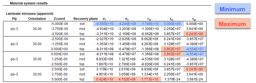
Figure 6.
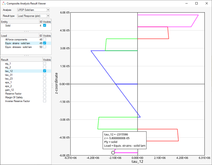
Figure 7.
Strength
Strength analysis calculates the failure loads for selected laminates for applying load components individually. Unit loads used for a load response/failure analysis and critical values are determined iteratively. Strength analysis is run through an analysis entity with Type: Strength. Mandatory analysis inputs are Entity (single or multi-selection of laminates) and FPF settings.
- Forces
- Moments
- Stresses (in-plane, flexural, out-of-plane)
- Strains (in-plane, flexural)
- Curvatures
- Failure mode and critical ply ID for each critical load
Composite Plate Loads
Composite stress toolbox utilizes 3 types of load vectors to calculate laminate load response. Each load vector consists of different load components. The components are listed in the table below.
| Type | Components |
|---|---|
| Forces and moments | N_x, N_y, N_xy, M_x, M_y, M_xy, Q_x, Q_y |
| Strains and curvatures | Epsilon_x, Epsilon_y, Gammy_xy, Kappa_x, Kappa_y, Kappa_xy |
| Homogenized stresses | Sigma_x, Sima_y, Tau_xy, Sigma^f_x, Sigma^f_y, Tau^f_xy, Tau_zx, Tau_yz |
First Ply Failure Methods
The First Ply Failure Method is a collection of mainly composite failure criteria, that can be utilized within the certification framework and composite stress toolbox. The latter are applicable to Strength and Load response/failure analysis. They can be created from certification ribbon tools or directly from the right-click menu of the Composite Browser.
Workflow
To set up and run an analysis:
- Create and edit all participating entities (materials, plies, laminates, composite plate loads, first ply failure methods).
- Right-click on Composite Browser white space or the Analyses folder to create an analysis entity.
- Select the analysis type.
- Select participating entities according to analysis type.
- Run using the analysis’ right-click menu option Run….
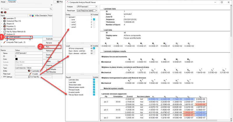
Figure 8.
Solver Specific Details
Entities created in the Composite Browser are assigned the most common solver card for a typical ply-based model. Properties and Shapes are filtered based on solver card to only display appropriate cards for a ply-based model. Additionally, in the OptiStruct profile, the appropriate card is set for laminate and ply entities upon creation.
| Entity | Supported Cards |
|---|---|
| Laminate | STACK |
| Material | MAT1, MAT8, MAT9OR |
| Ply | PLY |
| Zone | None |
| Entity | Supported Cards |
|---|---|
| Laminate | Via property *SHELL_SECTION_COMPOSITE |
| Material | *MATERIAL, with type ISOTROPIC, ENGINEERING CONSTANTS or LAMINA |
| Ply | None |
| Zone | None |
| Entity | Supported Cards |
|---|---|
| Laminate | Via property PCOMPP realized to PCOMP or PCOMPG |
| Material | MAT1, MAT8, MATORT |
| Ply | None |
| Zone | None |