Central Composite Design (CCD)
Central Composite Design contains an imbedded factorial or fractional factorial design with center points that are augmented with a group of star points that allow the estimation of curvature.
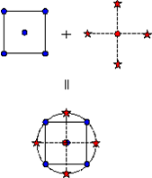
Figure 1. Generation of a Central Composite Design for Two Factors
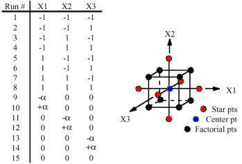
Figure 2. Generation of a Central Composite Design for Three Factors
| CCD Type | Terminology | Definition |
|---|---|---|
| Circumscribed | CCC | Designs are the original form of the central composite design. The star points are at some distance α from the center, based on the properties desired for the design and the number of factors in the design. The star points establish new extremes for the low and high settings for all factors. These designs have circular, spherical, or hyperspherical symmetry and require five levels for each variable. Augmenting an existing factorial or resolution V fractional factorial design with star points can produce this design. |
| Inscribed | CCI | Uses the variable settings as the star points and creates a
factorial or fractional factorial design within those limits (in
other words, a CCI design is a scaled down CCC design with each
variable level of the CCC design altered to generate the CCI
design). This design also requires five levels of each
variable. Note: Used for situations in which the limits
specified for variable settings are truly
limited.
|
| Face Centered | CCF |
The star points are at the center of each face of the factorial space, so α = ± 1. This variety requires three levels of each variable. Augmenting an existing factorial or resolution V design with appropriate star points can also produce this design. |
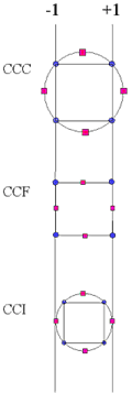
Figure 3. Comparison of the Different Types of Central Composite Designs
The Box Behnken design and the CCF Central Composite Design can be visualized as near compliments of each other. They both essentially suppress selected runs from a Full Factorial matrix in an attempt to maintain the higher order surface definition. For example, for three three-level variables, the Full Factorial run size is 27. The central composite plan drops all of the middle edge nodes, resulting in only fifteen runs. The Box Behnken design is nearly the opposite in that it uses the twelve middle edge nodes and the center node to fit a 2nd order equation. Central Composite Design plus Box Behnken becomes a Full Factorial with extra samples taken at the center.
Usability Characteristics
- Generally used for fitting a second-order response surface.
- In HyperStudy, the number of centre runs and axial
distance, a, are parameters that you need to enter. HyperStudy also offers some preset values for a.
Preset Name Axial Distance No. of Centre Runs Rotatable 2 User Defined Orthogonal 1.41421 User Defined Rotatable & Orthogonal 2 12 On Face 1 User Defined User Defined User Defined User Defined - The total number of runs is a function of the number of input variables and the number of center points as the Total runs = 2^k + 2k + N center points (k = input variables).
- When using Central Composite Design, HyperStudy has a limit of 20 input variables.
- Any data in the inclusion matrix is combined with the run data for post-processing. Any run matrix point which is already part of the inclusion data will not be rerun.
Settings
| Parameter | Default | Range | Description |
|---|---|---|---|
| Axial Distance | 0 | 0 | Automatically calculated when ityp is 1 ~ 4; it can be modified when ityp = 5. |
| Inscribe | On | Off or On | Choose whether to force the points within the input variable
bounds or not.
|
| Center Runs | 1 | Automatically determined when ityp = 3; you can modify it if ityp is not equal to 3. | |
| Type | Rotatable |
|
Type of axial scaling. |
| Use Inclusion Matrix | Off | Off or On | Concatenation without duplication between the inclusion and the generated run matrix. |