MV-100: Introduction to the MotionView Environment
In this tutorial you will learn how to open and save a model in MotionView, work with pages in a session, and switch HyperWorks Desktop clients.
- Invoking MotionView
-
- In Windows, click ..
OR
- In Linux, invoke
~hw_install/altair/scripts/mviewin an open terminal (where~hw_installis the location where HyperWorks is installed).
- In Windows, click ..
- The MotionView Interface
- MotionView is one of the clients that reside
under the HyperWorks Desktop (HWD) framework. The
framework provides a common layout for all clients. Other clients that are
available under this framework are: HyperMesh,
HyperView, HyperGraph 2D, HyperGraph 3D, MediaView,
TextView, and TableView. The client is selected, or changed, using
the Client selector drop-down menu:
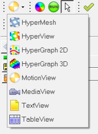
Figure 1.The image below shows the HWD graphical user interface with MotionView activated as the client: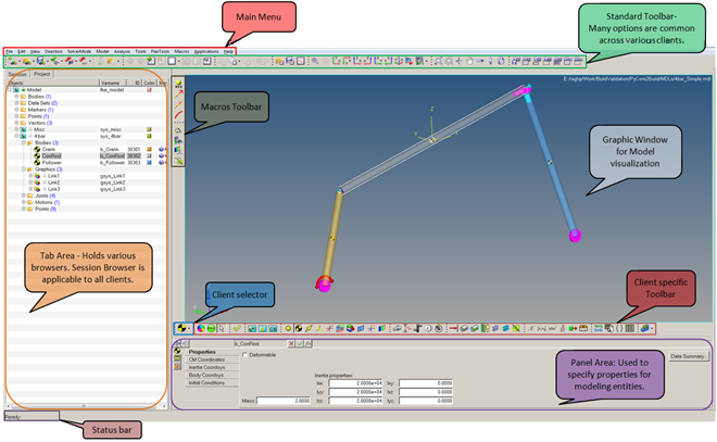
Figure 2.
- Main Menu
- The Main menu bar includes all functionalities that are available
through the various toolbars. Additionally, the Main menu contains other
useful utilities like FlexPrep, Import CAD/FEM, Macros, etc.

Figure 3.Note: The Main menu varies between the different clients of HyperWorks Desktop. - HWD Standard Toolbars
- Toolbars provide quick access to commonly used features. HyperWorks Desktop toolbars are static and will not
change, regardless of which application is active. Some of the toolbars
become inactive when different clients are selected. In the table below,
all of the HWD toolbars are introduced. Please be sure to note the
toolbars that are not applicable to the MotionView client.
Toolbar Purpose Image Client Selector Selecting the HWD client from the drop-down list. 
Standard Options for file management (Creating, Editing, Saving, Importing, and Exporting of files etc.). 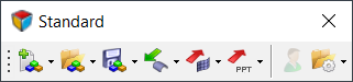
Page Controls Options to: - Create and Delete pages and windows.
- Expand, Swap, and Synchronize selected windows.
Note: To navigate through different pages of a session, use the Previous Page or Next Page buttons (located at the upper right corner of the window, below the menu bar area and above the graphics area). See the Page Display and Navigation Area topic for additional information.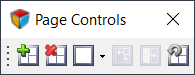
Page Edit Options to manage pages and windows of a session (Cut, Copy, Paste, and Overlay of a page and window). 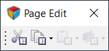
Animation Toolbar Provides controls for the animation of results. 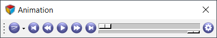 Note: Available in HyperView and HyperGraph only.
Standard Views Options to view model in different orthogonal views. 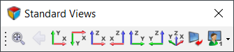
3D View Controls Options to control the 3D view of the model (Rotate, Pan, Zoom, etc.). 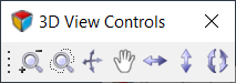
2D View Controls Options to control the 2D view of plots (Pan, Zoom, etc.). 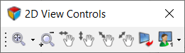 Note: Available in HyperGraph only.
Reports Options to Create/Open/Define Report Templates. 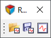
Scripting Options to Create/Open/Debug/Run Tcl and HyperMath scripts. 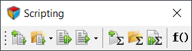
Image Capture Capture Image/Video of the active page. 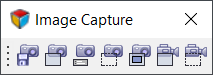 Note: Please refer to the HyperWorks Desktop User’s Guide > Graphical User Interface > Toolbars topic for a detailed explanation of each toolbar listed above.
 - Client Specific Toolbars
- Client specific toolbars provide access to options required for pre- or
post-processing of FEA/MBD models. MotionView has a set of toolbars for building an MBD model. Each MotionView toolbar group provides access to
entities with similar characteristics. For example, all entity such as
Joints and Motions are grouped in the Constraint toolbar. The table
below shows MotionView toolbars with a brief
explanation of their usage.
Toolbar Purpose Image General Actions Options to render graphics, provide access to the Run panel (change solver settings and submit jobs to the solver), and the Entity Selector.
Depressing the Entity Selector icon
 indicates the graphic
screen is in entity selection mode. If no other
entity icons are depressed, the selection is not
filtered to a particular entity (any entity that
has a graphical representation on the screen can
be selected).
indicates the graphic
screen is in entity selection mode. If no other
entity icons are depressed, the selection is not
filtered to a particular entity (any entity that
has a graphical representation on the screen can
be selected).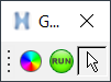
Container Entity Select/Add container entities like Assemblies, Systems, and Analyses. 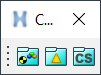
Reference Entity Select/Add entities like Points, Bodies, Vectors, Markers, etc. 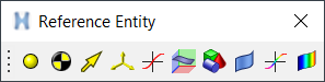
Constraint Select/Add constraint entities like Joints, Motions, Couplers, etc. 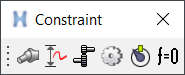
Force Entity Select/Add force entities like multi-axial Forces, Spring Dampers, Bushings, Beams, Contacts, etc. 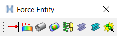
Control Entity Select/Add entities like Solver Variables, Solver Arrays, SISO Controller, Differentials, and Sensors which are useful in defining controlled simulations. 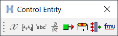
General MDL Entity Select/Add general MDL entities like Datasets, Templates, Forms and Output Requests. 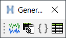
Model Check Checks the model. 
Point Macros Access point creation macros useful in adding points with respect to a reference frame, along a vector, along a curve and at an arc center. 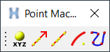
Other Macros Other macros useful in modeling and debugging: calculate angles, find connected entities, create markers for a deformable surface and contact properties editor. 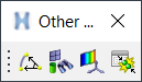
- A left click on an entity icon sets the filter to select that particular
entity from the graphic screen, while a right-click on a toolbar icon
enables adding that entity to the model (see the Points example
below):
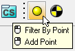
Figure 4.- Left mouse click - Filters selection to a Point entity.
- Right mouse click - Opens the Add Point dialog to add a Point.
Note: Mouse over the icons to display a tip about the type of entity that can be selected or added. - Browsers
-
- Tab Area
- The tab area docks different browsers, the purpose of the browsers is to navigate through the hierarchy tree and execute some operations specific to the selected items. Available for all clients is the Session Browser Browser, which allows you to browse to the different pages or windows in an HWD session, as well as execute certain page and window operations. In addition to the Session Browser, client specific browsers are shown based on the active window. For example, when the MotionView is active client in the working window, the MotionView Project Browser is shown; similarly, when HyperView is active, the Results Browser is shown. Specifically, the MotionView Project Browser helps you browse/select different modeling entities, in addition to executing certain modeling operations. Other browsers include the Organize browser (used for data management and collaboration) and the Process Manager (used for process automation). Please refer to the client specific online help regarding the available browsers. Finally, browsers can be placed on either side of the graphic window (Left/Right/Both) through the Menu bar by using the menu options.
- Mouse Options in the Project Browser
- A left mouse click on an entity in the Project Browser selects that entity and the
details of entity are displayed in the Panel area (see the
example below):
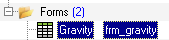
Figure 5.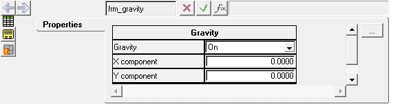
Figure 6.A right click on an object brings up a context menu with options that are relevant to the selected object.
For example, a right click on a Point entity brings up a context menu that provides options to either: Deactivate, Rename, Add, Delete, or Cut the point entity along with options to filter entities.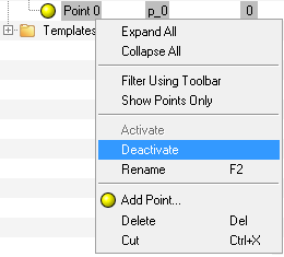
Figure 7.Similarly, a right mouse click on the Model (the topmost folder in the browser hierarchy) displays up a context menu with options useful in model building.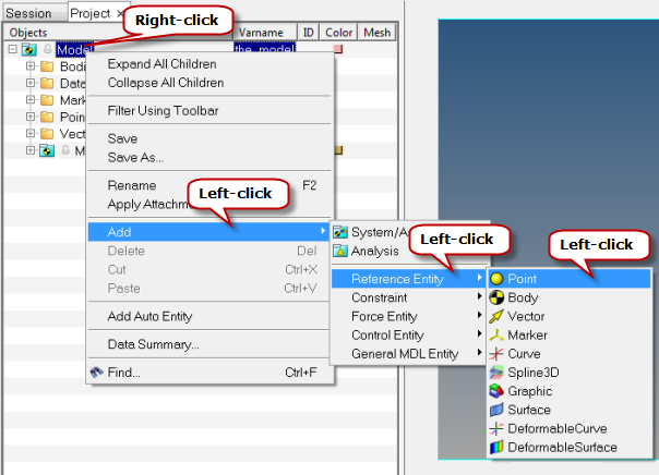
Figure 8.
- Panel Area
- Below the client specific toolbar is the panel area where you can view
and modify the various values and properties of a selected entity.
Panels may have several tabs which organize the various properties and
values of the entity type selected. For example, the Spring Damper panel
has the connectivity information and properties displayed in three tabs
(as shown below):
- Connectivity tab
- Allows you to specify the type of spring, the bodies to
attach, and the attachment points.
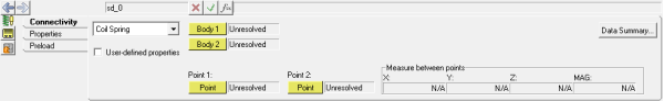
Figure 9. - Properties tab
- Allows you to set the stiffness and damping properties of a
spring.
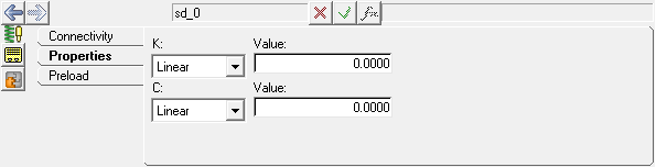
Figure 10. - Connectivity tab
- Allows you to set a 'preload' on a spring by specifying a
force value or spring free length.
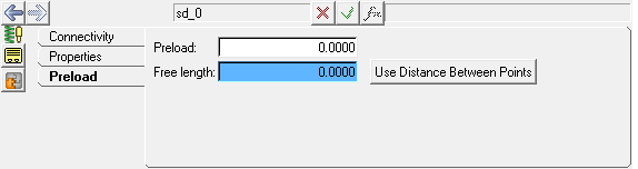
Figure 11.
- Graphics Window
- Graphics window is the model visualization area where you can
interactively work on the model. The following table illustrates the various mouse clicks available for model visualization:
Operation Action Left click on an entity like a Point, Graphic, etc. (while the Entity Selector and an entity icon is depressed in the toolbar). Selection (the selected entity is highlighted by a white boarder around it). Hold the left mouse button and move over the model (while the Entity Selector and an entity icon is depressed in the toolbar). Displays the entity name on the mouse tooltip and selects the entity upon releasing mouse button. Right-click on a model entity. Displays a context menu with various options: Select, Cut, and Delete against each entity name. Ctrl + Left mouse button Rotates the model (observe the mouse tooltip). Ctrl + Left click Picks the center of rotation. Ctrl + Right mouse button Translates/Pans the model. Ctrl + Middle mouse button Selects the window to fit. Ctrl + Middle click Fits the model to the window. The controls for the mouse can be found under :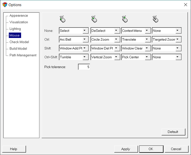
Figure 12.You can customize the mouse controls using this dialog.Note: The items under the Main Menu, Browser, and Client specific toolbars differ from client to client.
Open a MotionView Model File
In this step, you will learn how to open a MotionView Model file.
-
Open the model by doing one of the following:
- In the Standard toolbar, click the
 (Open Model) icon.
- From the File menu, select .
- In the Standard toolbar, click the
-
From the Open Model dialog, click the
SingleCylinderEngine_model.mdl located in your
<working directory>.
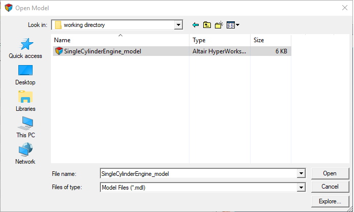
Figure 13.MDL stands for "Model Definition Language". MDL is an ASCII programmable language for modeling in MotionView. See the MotionView Reference Guide for details about the different MDL statements. -
Click Open.
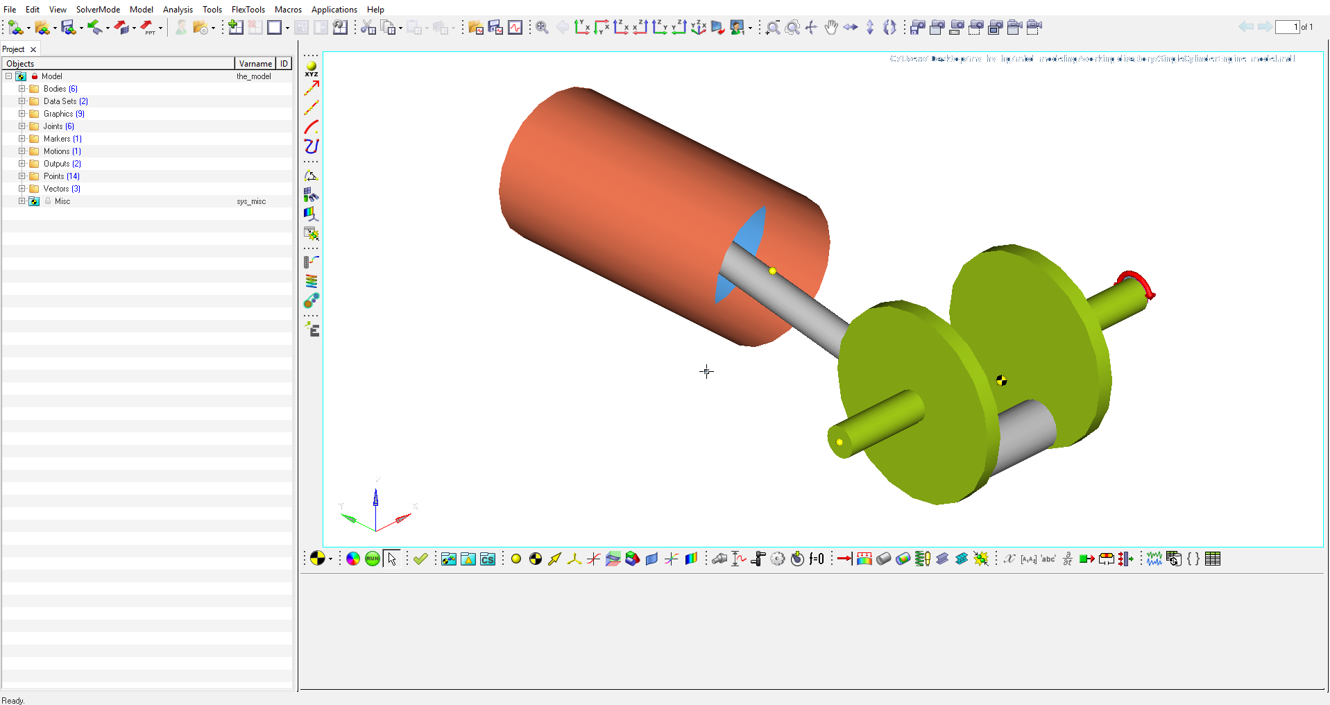
Figure 14.The single cylinder engine model will display in the modeling window. Upon successful loading of a model into MotionView, the status bar will display the Ready message.The Project Browser lists all of the entities in the model.
-
In the browser, click the Expand
 /Collapse
  button of each entity folder
(Bodies, Points, Joints, Motions, and so on.)
This will expand the folder in the Project Browser. Use the mouse controls in the modeling window to rotate, pan, and zoom the model.
button of each entity folder
(Bodies, Points, Joints, Motions, and so on.)
This will expand the folder in the Project Browser. Use the mouse controls in the modeling window to rotate, pan, and zoom the model. -
Next to the Bodies folder, click the Expand button
 .
.
-
Click on the CRANK_SHAFT body to review its
properties.
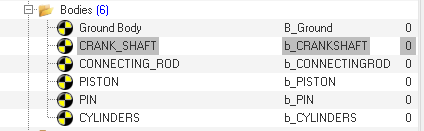
Figure 15.The corresponding entity panel (Bodies in this case) is displayed in the bottom of the window.Note: Each entity will have a label and a unique variable name. For example, the crank shaft body has a label of CRANK_SHAFT and a variable name of b_CRANKSHAFT. -
From the Properties tab, view the Mass and Inertia properties of the
body.
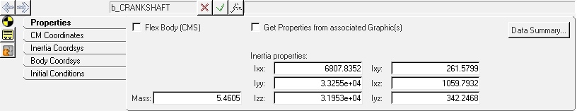
Figure 16. -
Click on CM Coordinates tab to review the CM point and
orientation of the body.
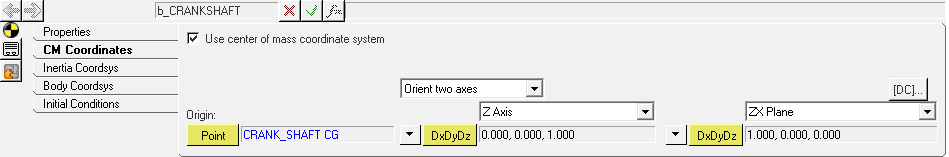
Figure 17.The Origin point defines the body CG location. The orientation is defined with respect to global reference frame using direction cosines DxDyDz.
Select and Modify a Motion
In this step you will modify the crank shaft rotational velocity to 10rad/sec.
-
On the Constraint toolbar, left-click the
 (Motion) icon.
-
Identify the CrankShaft Rotation in one of two ways:
- In the modeling window, hold down the left mouse button to identify the Crankshaft Rotation. Hold your cursor over the Crankshaft rotation and release the button to select it.
- In the Project Browser, find the Motions entity and
click (Expand). Then select Crankshaft
Rotation.
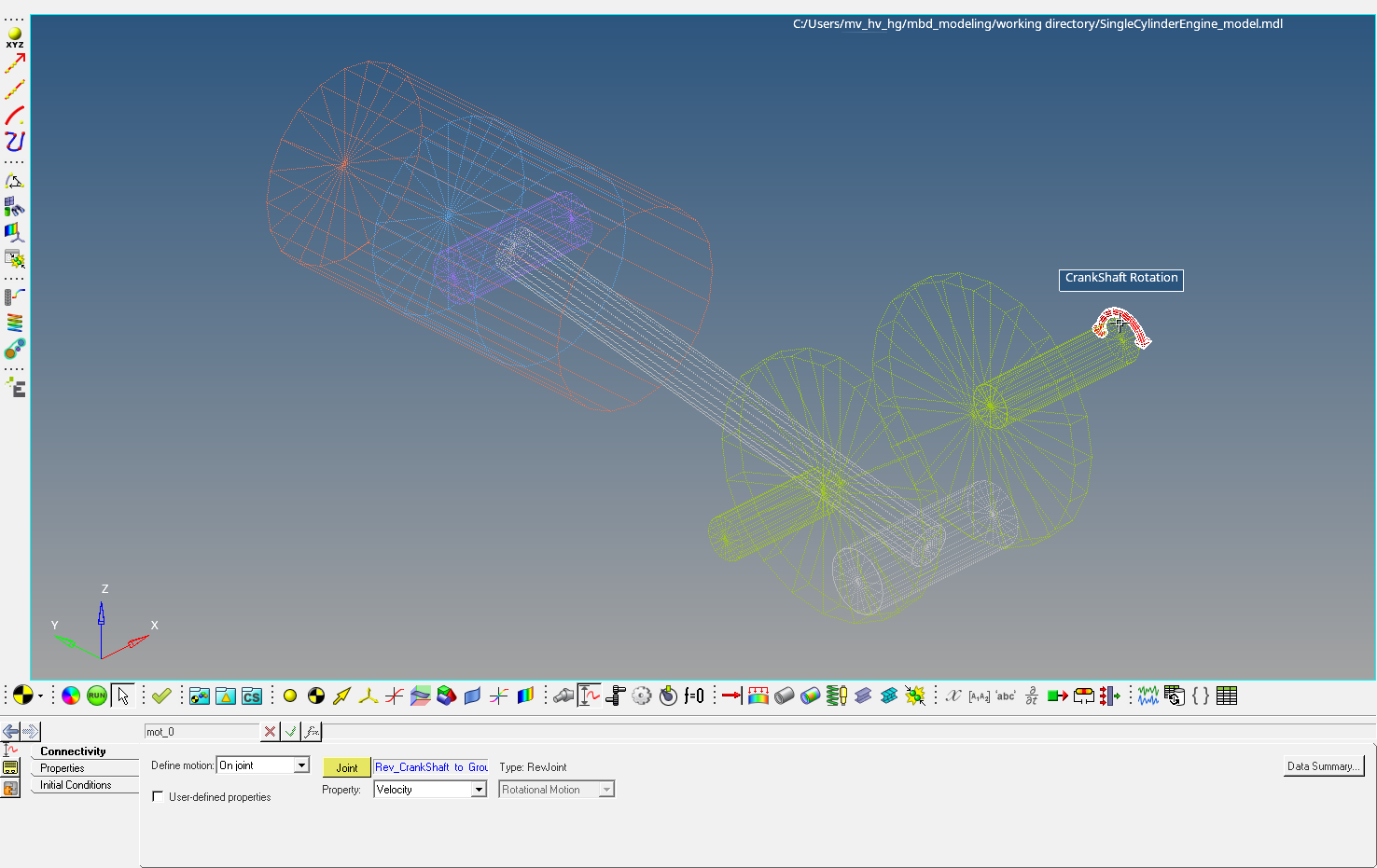
Figure 18.Note: Implicit graphics are displayed for all applicable entities, allowing you to visualize their location and orientation. See the MotionSolve User's Guide for details about controlling the visualization of implicit graphics. -
In the Value field, enter 10.
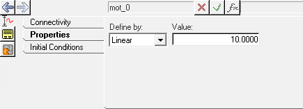
Figure 19.
Save a MotionView Model
In this step you will learn to save your MotionView model to your <working directory>.
-
From the menu bar, click .
The Save As Model dialog will be displayed.Note: You can also click the
 (Save Model) icon on the Standard toolbar to the
save the file in <working directory> with the
existing name. If the model is new, you will be prompted to input the name
of the model.
(Save Model) icon on the Standard toolbar to the
save the file in <working directory> with the
existing name. If the model is new, you will be prompted to input the name
of the model. -
In your <working directory>, name the file
SingleCylinderEngine_model_10rad_per_sec.mdl.
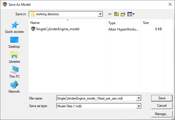
Figure 20.
Solve the Model
In this step you will invoke MotionSolve to solve your model.
-
On the General Actions toolbar, click
 (Run).
-
From the Run panel, click the Run button.
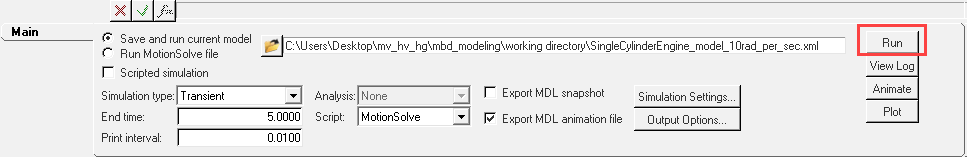 Figure 21. This will invoke MotionSolve and solve the model. The HyperWorks Solver View window will appear and show the progress of the solution along with messages from the solver (Run log). This log is also written to a file with the extension .log to the solver file base name.
Add Pages to a Session
In this step you will learn how to add a page, change to different HyperWorks Desktop clients, change the page layout, and navigate between pages. You will also load the result files to view the animation and the plot.
-
From the Page Controls toolbar, click the
 (Add Page) icon.
This adds a new page with MotionView as the client.Note: The Add Page option adds a page with the current client (in this case, MotionView).
(Add Page) icon.
This adds a new page with MotionView as the client.Note: The Add Page option adds a page with the current client (in this case, MotionView). -
From the Select application drop-down menu, select HyperView.
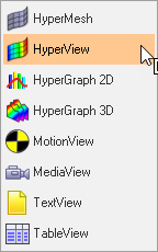
Figure 22. -
Load the model.
-
From the Load Model panel, click on the Select
File icon
 next to Load model.
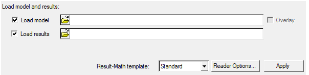
Figure 23.
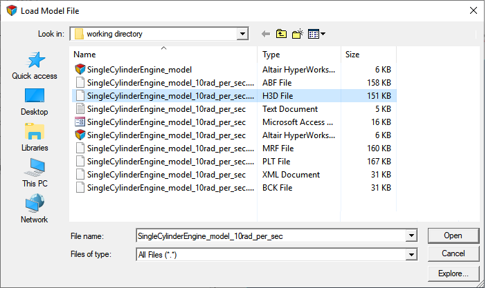
Figure 24.The file will populate the Load results field automatically.Note: H3D is an Altair binary file for HyperView. The H3D file contains both model and results data from a solver run. Please see the Appendix (below) for various use cases of H3D files in MotionSolve/MotionSolve. -
From the Load Model panel, click on the Select
File icon
-
Click Apply to load the
results.
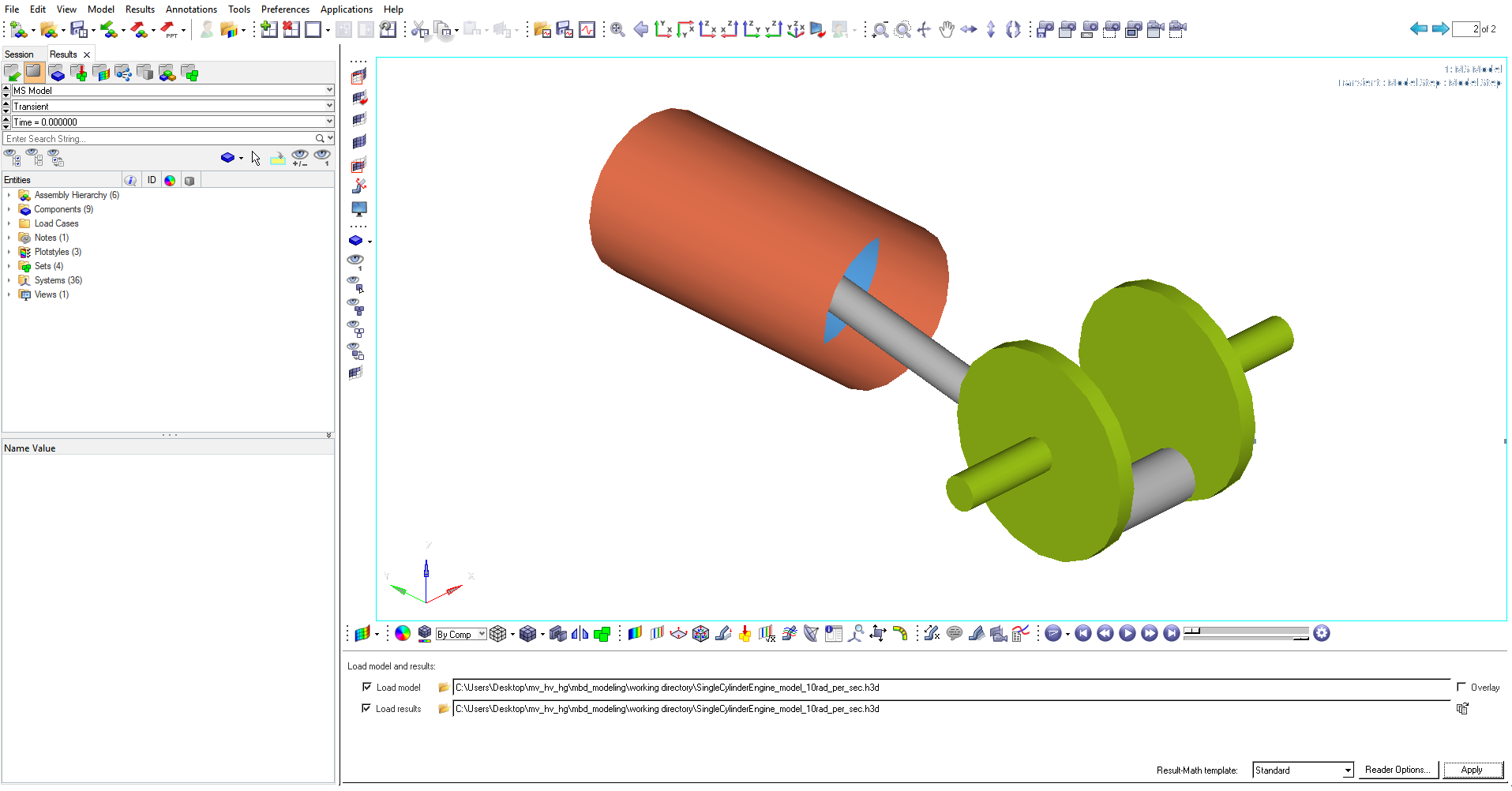
Figure 25. -
From the Animations toolbar, click the
 (Start/Pause Animation) button to animate the
results.
(Start/Pause Animation) button to animate the
results.
- Use the mouse controls for better visualization and understanding of the results.
-
Click the
 (Start/Pause Animation)
button again to stop the animation.
(Start/Pause Animation)
button again to stop the animation.
-
To plot the results, add a window to the current page.
-
From the Page controls toolbar, click the arrow
next to the Page Window Layout button
 .
.
-
Select the two window layout
 .
.
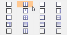
Figure 26.
-
From the Page controls toolbar, click the arrow
next to the Page Window Layout button
-
Use the Select application drop-down menu to change the application from
HyperView
 to HyperGraph 2D
 .
Note: The Client selector displays the icon of the current client (HyperGraph in this case).
.
Note: The Client selector displays the icon of the current client (HyperGraph in this case). -
Open the MotionSolve results file for your
model.
-
On the Curves toolbar, click the
 (Build Plots)
icon.
(Build Plots)
icon.
-
From the Build Plots panel, click
(Open File) next to Data File.
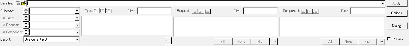
Figure 27.
-
On the Curves toolbar, click the
-
In the Open Data File dialog, navigate to your <working
directory> and select the MotionSolve
results SingleCylinderEngine_model_10rad_per_sec.abf
file.
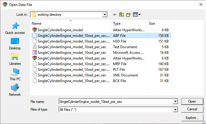
Figure 28.Note: ABF is the Altair Binary File for HyperGraph. Other output files from MotionSolve (.mrf and .plt) can also be used for reading results into HyperGraph. -
Plot the angular velocities for the crank shaft.
- For X Type, select Time.
- For Y Type, select Marker Velocity.
- For Y Request, select REQ/70000002.
- For Y Component, select Wx.
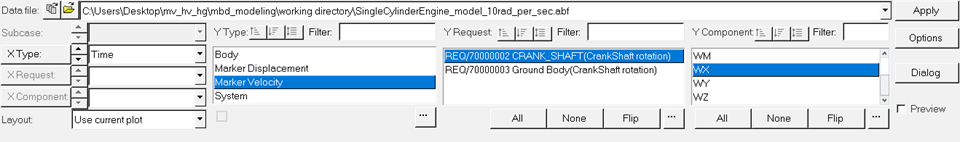
Figure 29.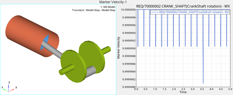
Figure 30. Two Window Layout (with HyperView and HyperGraph 2D)-
From the Animation toolbar click Start/Pause
Animation
to animate the
results.
Click on (Expand/Reduce Window) to expand
or reduce an active window.
(Expand/Reduce Window) to expand
or reduce an active window. Click on
 (Previous Page) or
  (Next Page) to navigate between pages 1 and
2.
(Next Page) to navigate between pages 1 and
2.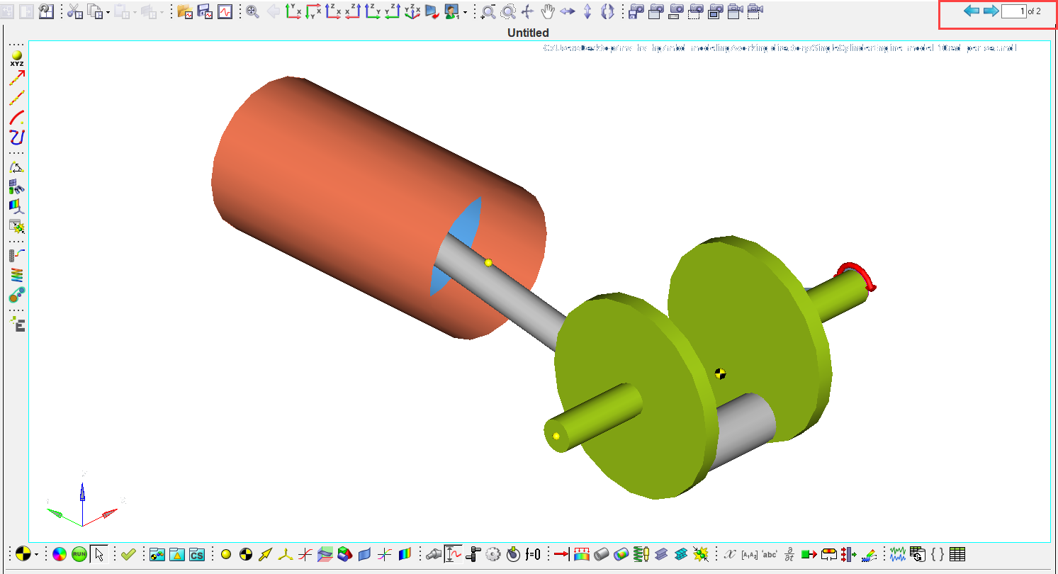
Figure 31. MotionView with Single Cylinder Engine Model
Save a Session File
In this step you will learn how to save your work as a session file.
-
In the working directory, name the file
mywork.mvw.
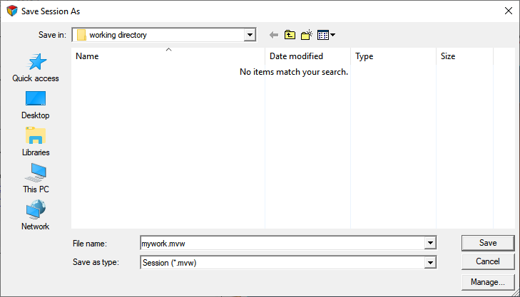
Figure 32.Note: A session file saves the complete HyperWorks Desktop data (the page, window, client, and results information). Please refer to the Appendix for details regarding the different types of HyperWorks Desktop files.
Open a Session File
In this step, you will learn how to open a session file in MotionSolve.
-
From the menu bar, click .
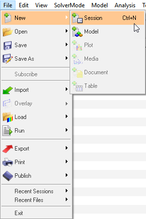
Figure 33.- There will be a message asking if you would like to discard all current session data and start a new session. Click Yes.
-
In the Open Session File dialog, select
mywork.mvw.
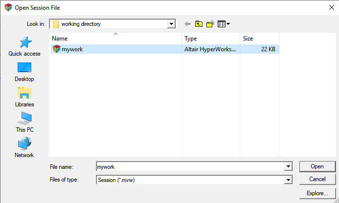
Figure 34. -
Click Open.
You have successfully opened your session file. Browse through the pages usingand icons.
Appendix
- HyperWorks Desktop File Types:
- Table 1
summarizes the different file types in HyperWorks Desktop
and the location where the file can be loaded and saved.
Table 1. Options for loading and saving different file types File Type Extension Window Mode Session script .mvw Any Report template .tpl Any MDL .mdl MotionView Animation .gra, .res (Adams and Optistruct), .h3d, .flx, .mrf HyperView Plot .req, .mrf, .abf, .plt, .res (Adams) HyperGraph Templex script, any text file .tpl, .txt TextView - H3D File Use Cases in MotionView/MotionSolve
- H3D is an Altair format for storing model and result information. In
general, an H3D file is used for post-processing results in HyperView; however the H3D file has a few other
use cases in MotionView/MotionSolve.
Table 2. Graphic H3D File This type of H3D contains Model information only. A graphical H3D file is an imported geometry into MotionView for visualization of a body. Flexbody H3D File This type of H3D contains Model and Flexible body information. Therefore, MotionView can use it as a graphic, as well as to represent a deformable body by accessing the modes, mass, and inertia information. HyperView can read it as both Model and Results, and also animate the mode shapes, modal displacements, stresses, and so on (if available). Results H3D File This type of H3D is written by MotionSolve. It contains Model and Results information. HyperView can read it as both Model and Results, and also animate the position, deformation, stresses, forces, and so on.
- Model Information – Nodes and Elements
- Flexible Body Information – Modes, Interface Nodes, Mass/Inertia
- Results – Position, Displacements, Stress, Strain, and so on