MV-2100: Introduction to Non-Linear Finite Element (NLFE) Analysis in MotionSolve
In this tutorial, you will learn about Non-Linear Finite Element formulation used in MotionSolve and about how to model NLFE bodies in MotionSolve.
- NLFE Formulation
-
MotionSolve uses Absolute Nodal Coordinate Formulation (ANCF) to model large displacement and large deformation (NLFE) bodies. The absolute nodal coordinate formulation[1] is developed based on finite element formulation and is designed for large deformation multibody analysis. In the absolute nodal coordinate formulation, slopes and displacements are used as the nodal coordinates instead of infinitesimal or finite rotations.
ANCF uses the shape function matrix, together with the nodal coordinates to describe arbitrary rigid body motion. For these reasons, the absolute nodal coordinate formulation leads to a constant mass matrix in two- and three-dimensional cases. The constant mass matrix simplifies the nonlinear equations of motion and, consequently, accelerates the time integration of the nonlinear equations of motion. Figure 1 shows a standard beam model[2] described in 2D plane using ANCF.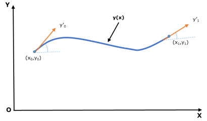 Figure 1. Euler–Bernoulli beam element
Displacement field, y(x) = s1(x)y0+ s2(x)y’0 +s3(x)y1+ s4(x)y’1
- s1 to s4 are shape functions of beam.
- x0, y0, x1, and y1 are nodal coordinates of 2 grids.
- y’0 and y’1 are slope coordinates (gradients) at 2 grids.
The absolute nodal coordinate formulation has been applied to a wide variety of challenging nonlinear dynamics problems that include belt drives, rotor blades, elastic cables, leaf springs, and tires.
- Non-linear Finite Element Capabilities in MotionSolve
-
- All type of linear and non-linear elasticity is supported i.e. Isotropic, Orthotropic, Anisotropic and Hyper elasticity.
- Geometric stiffening induced due to elastic forces.
Modeling non-linear behavior above the elasticity limit (like plastic deformation, strain hardening, fracture etc.) is not supported. In the current version, MotionView supports modeling of 1D line elements only (Beam and Cable elements). Beam elements can have 18 types of cross-sections and the dimensions of the cross-section can be changed linearly in the axial direction. Beam elements can resist axial, shear, torsion and bending loads. The Cable element maintains a constant cross-section, thus it can resist only axial and bending loads.
This tutorial contains two exercises:- Cantilever beam bending.
- Uniaxial tension of rubber.