User Interface Layout
View the main elements and terminology in the WallMan graphical user interface (GUI).

-
- Standard toolbar
- The standard toolbar gives access to commonly used menu items including New Database, Open Database, and Save Database.
-
- View toolbar
-
The view toolbar gives access to tools related to navigating the 2D views, changing the view, single wall view, and navigating the 3D view.
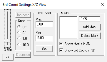
The 2D views in WallMan show the database as a cross-section with a specified plane. The plane moves along the third axis (for example, the Z-axis in the X/Y view). Click the icon to modify the
cut plane.
Figure 1. The 3rd Coord Settings X/Y View dialog.
-
- Objects toolbar
- The objects toolbar gives access to tools to create indoor objects, outdoor objects, and tools to select these objects.
-
- Status bar
- The Status bar is a small toolbar that gives quick access to absolute coordinates at the location of the mouse cursor in the 2D view and also displays the currently active 2D window.
-
- Preprocessing toolbar
- The preprocessing toolbar gives access to tools such as New Project, Open Project, Save Project, and defining the preprocessing area.
-
- Indoor lego toolbar
- The indoor lego toolbar gives access to basic wall combinations for indoor database creation, for example, Rectangular room, T-shaped room, Stairs, and Roof.
-
- Clutter toolbar
- The clutter toolbar gives access to tools such as editing or displaying
clutter databases.Note: A clutter1 database is a pixel matrix and contains information about the land usage at a given location, for example, forest, water, residential or industrial.
-
- Cross-section view at the X/Y plane
- The active view (for this example) as indicated by the text (X/Y) in red. A cross-section view of the model in the X/Y cut plane is displayed.
-
- Cross-section view at the X/Z plane
- A cross-section view of the model in the X/Z cut plane is displayed.
-
- 3D view
- A 3D view of the model showing the location of the three cut planes ( X/Y plane, X/Z plane, and Y/Z plane) in purple.
-
- Cross-section view at the Y/Z plane
- A cross-section view of the model in the Y/Z cut plane is displayed.