Standard Ray Tracing (SRT)
The standard ray-tracing model (SRT) performs a rigorous 3D ray-tracing prediction which results in very high accuracy but at the cost of a large computational effort.
Deterministic models are used to model the propagation of radio waves physically. Therefore the effect of the environment on the propagation parameters can be taken into account more accurately. Another advantage is that deterministic models make it possible to predict several propagation parameters. For example, the path loss, impulse response, and angle-of-arrival can be predicted at the same time.

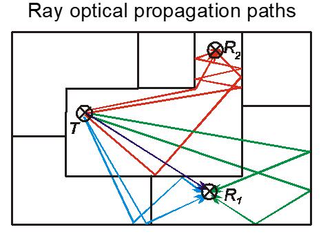
Figure 1. Principle of ray-optical models.
As smaller wavelengths (higher frequencies) are considered, the wave propagation becomes similar to the propagation of light. Therefore a radio ray is assumed to propagate along a straight line influenced only by refraction, reflection, diffraction or scattering (see Figure 1) which is the concept of geometrical optics (GO). The criterion taken into account for this modeling approach is that the wavelength should be much smaller in comparison to the extension of the considered obstacles, which are typically the walls of a building. At the frequencies used for mobile communication networks, this criterion is also sufficiently fulfilled inside buildings.
- ray-tracing
- ray launching
The so-called standard ray-tracing model (SRT) performs a rigorous 3D ray-tracing prediction which results in very high accuracy. Due to the determination of the individual paths, the computational effort is very large. Therefore several acceleration techniques both with and without loss of accuracy are developed and integrated into this rigorous 3D approach.
This model has a long computation time because only small parts of the prediction are preprocessed, and every propagation path is analytically determined. The initialization data is stored in a .idw file. This file is created at the first prediction run. The computation time of subsequent predictions that are based on the new .idw database is thus reduced. For this purpose, a new project based on the .idw database has to be created.
Propagation Paths
The computed propagation paths can either be selected by using a selection file (.sel) and choosing the option Only user defined propagation paths. Usually, however, the option Number of interactions is used. Each transmission through a wall, each reflection at a wall and each diffraction at an edge counts as an interaction.
The value Max. defines the maximum number of interactions that are allowed for each propagation path. The appropriate value depends on the building structure. If, for example, the building has a corridor that runs around a corner three times, then it would be better to compute more interactions because multiple diffractions are needed to reach all prediction pixels. The same occurs if a building has a structure where the rays have to pass many walls to reach every point of the building because then more transmissions are needed.
The only constraint is that the computation time naturally increases if more interactions are computed. On the other hand, if too few interactions are computed, the accuracy decreases. For the case of the unreached pixels, an empirical model should be used, but with decreased accuracy.
As a basic rule, an appropriate setting for Max. value would be 2 – 4, depending on the building structure.
Computation of Each Ray’s Contribution
The deterministic model uses Fresnel equations for the determination of the reflection and transmission loss and the GTD/UTD for the determination of the diffraction loss. This model has a slightly longer computation time and uses three physical material parameters (permittivity, permeability, and conductivity).
The empirical model uses five empirical material parameters (minimum loss of incident ray, the maximum loss of incident ray, loss of diffracted ray, reflection loss and transmission loss). For correction purposes or the adaptation to measurements, an offset to those material parameters can be specified.
The empirical model has the advantage that the required material properties are easier to obtain compared to the physical parameters for the deterministic model. Also, the parameters of the empirical model can more easily be calibrated with measurements. It is, therefore, easier to achieve high accuracy with the empirical model.
The effect of bookshelves and cupboards covering considerable parts of walls is taken into account by including an additional loss for the wall’s penetration (transmission) loss. An additional loss of 3 dB has been observed to be appropriate. This additional loss is introduced in the context of the walls covered by bookshelves, cupboards or other large pieces of furniture. Furthermore, it was found necessary to set an empirical limit for the wall transmission loss which otherwise becomes very high when the angle of incidence is large.