Calculating the Port Parameters and Field Data
For this example, a plate4prt.pfs file containing the far fields and near fields for each port is provided with the multiport S-parameter Touchstone file.
-
Specify the input method for the Multiport
post-processingapplication macro.
For this example, measurement data is used as input.
Tip: Find the examples in the <FEKO_SHARED_HOME> directory:<FEKO_SHARED_HOME>/installedapplicationmacrolibrary/POSTFEKO/MultiportCalculation/examples.
-
In the Reference impedance (Z0) field, enter 50
Ohm.
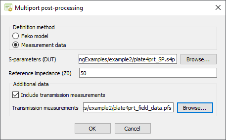
Figure 1. The Multiport post-processing dialog.
The Processing options dialog is displayed. -
In the Reference impedance (Z0) field, enter 50
Ohm.
-
Specify the processing options and data handling.
-
[Optional] In the Results prefix (optional)
field, specify a result prefix.
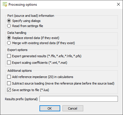
Figure 2. The Processing options dialog.
The Select transmission measurement data dialog is displayed. -
[Optional] In the Results prefix (optional)
field, specify a result prefix.
-
Specify the transmission measurement data.
-
Under Near fields, map the near field data to
the correct port.
- Port1: NearField_Port_1
- Port2: NearField_Port_2
- Port3: NearField_Port_3
- Port4: NearField_Port_4
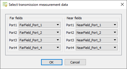
Figure 3. The Select transmission measurement data dialog.
The Select ports to load dialog is displayed. -
Under Near fields, map the near field data to
the correct port.
-
Specify the non-active (terminated) ports.
For this example, only Port_3 and Port_4 are non-active (terminated) ports.
-
Under Load specification type, select
Point loads (multiple 1-port loads of varying
types) to specify the individual loads.
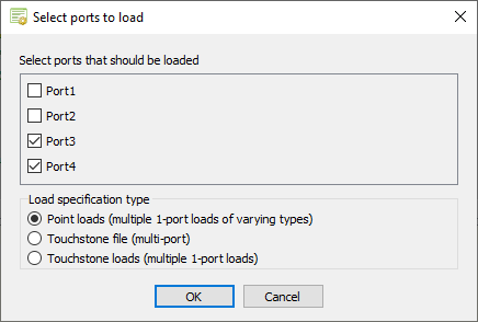
Figure 4. The Select ports to load dialog.
The Load type for terminated ports dialog is displayed. -
Under Load specification type, select
Point loads (multiple 1-port loads of varying
types) to specify the individual loads.
-
Specify the load types for the non-active (terminated) ports.
-
In the Load type for port Port_4 field, select
Complex load.
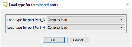
Figure 5. The Load type for terminated ports dialog.
The Select load parameters dialog is displayed. -
In the Load type for port Port_4 field, select
Complex load.
-
Specify the load values for the non-active (terminated) ports.
-
Under Port_4 (Complex impedance), specify the
following values in Ohm:
- Real component: 75
- Imaginary component: 0
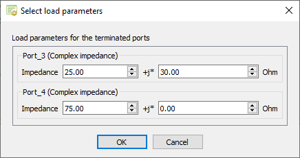
Figure 6. The Select load parameters dialog.
The Select source parameters dialog is displayed. -
Under Port_4 (Complex impedance), specify the
following values in Ohm:
-
Specify the excitations for the active ports and the load impedances.
-
Specify the excitation for Port_2.
- Under Port_2, in the Definition method drop-down list, select Direct connection.
- Specify the following values:
- Amplitude: 2 V
- Phase: 0°
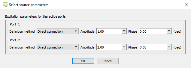
Figure 7. The Select source parameters dialog
The new results are calculated and available in POSTFEKO in the Project Browser under Stored data.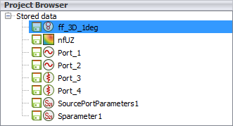
Figure 8. The multiport results under Stored data. -
Specify the excitation for Port_2.