 Package Modelica.Electrical.Analog.Ideal
Ideal electrical elements such as switches, diode, transformer, operational amplifier
Package Modelica.Electrical.Analog.Ideal
This package contains electrical components with idealized behaviour. To enable more realistic applications than it is possible with pure realistic behavior some components are improved by additional features. E.g. the switches have resistances for the open or close case which can be parametrized.
Extends from Modelica.Icons.Package (Icon for standard packages).
| Name | Description |
|---|---|
AD_Converter | Simple n-bit analog to digital converter |
CloserWithArc | Ideal closing switch with simple arc model |
ControlledCloserWithArc | Controlled ideal electrical closer with simple arc model |
ControlledIdealClosingSwitch | Controlled ideal electrical closer |
ControlledIdealCommutingSwitch | Controlled ideal commuting switch |
ControlledIdealIntermediateSwitch | Controlled ideal intermediate switch |
ControlledIdealOpeningSwitch | Controlled ideal electrical opener |
ControlledOpenerWithArc | Controlled ideal electrical opener with simple arc model |
DA_Converter | Simple digital to analog converter |
IdealClosingSwitch | Ideal electrical closer |
IdealCommutingSwitch | Ideal commuting switch |
IdealDiode | Ideal diode |
IdealGTOThyristor | Ideal GTO thyristor |
IdealGyrator | Ideal gyrator |
IdealIntermediateSwitch | Ideal intermediate switch |
IdealizedOpAmpLimted | Idealized operational amplifier with limitation |
IdealOpAmp | Ideal operational amplifier (norator-nullator pair) |
IdealOpAmp3Pin | Ideal operational amplifier (norator-nullator pair), but 3 pins |
IdealOpAmpLimited | Ideal operational amplifier with limitation |
IdealOpeningSwitch | Ideal electrical opener |
IdealThyristor | Ideal thyristor |
IdealTransformer | Ideal transformer core with or without magnetization |
IdealTriac | Ideal triac, based on ideal thyristors |
Idle | Idle branch |
OpenerWithArc | Ideal opening switch with simple arc model |
Short | Short cut branch |
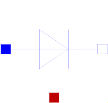 Model Modelica.Electrical.Analog.Ideal.IdealDiode
This is an ideal diode, for details see partial model IdealSemiconductor
The diode is conducting if voltage > Vknee.
The diode is locking if current < Vknee/Goff.
Extends from Modelica.Electrical.Analog.Interfaces.IdealSemiconductor (Ideal semiconductor).
| Type | Name | Default | Description |
|---|---|---|---|
Resistance | Ron | 1e-5 | Forward state-on differential resistance (closed resistance) |
Conductance | Goff | 1e-5 | Backward state-off conductance (opened conductance) |
Voltage | Vknee | 0 | Forward threshold voltage |
Boolean | useHeatPort | false | =true, if heatPort is enabled |
Temperature | T | 293.15 | Fixed device temperature if useHeatPort = false |
| Type | Name | Description |
|---|---|---|
PositivePin | p | Positive electrical pin |
NegativePin | n | Negative electrical pin |
HeatPort_a | heatPort | Conditional heat port |
 Model Modelica.Electrical.Analog.Ideal.IdealThyristor
This is an ideal thyristor, for details see partial model IdealSemiconductor
The thyristor is conducting if voltage > Vknee AND fire = true.
If fire gets false, the current has to fall below Vknee*Goff, then the thyristor gets locking.
Extends from Modelica.Electrical.Analog.Interfaces.IdealSemiconductor (Ideal semiconductor).
| Type | Name | Default | Description |
|---|---|---|---|
Resistance | Ron | 1e-5 | Forward state-on differential resistance (closed resistance) |
Conductance | Goff | 1e-5 | Backward state-off conductance (opened conductance) |
Voltage | Vknee | 0 | Forward threshold voltage |
Boolean | useHeatPort | false | =true, if heatPort is enabled |
Temperature | T | 293.15 | Fixed device temperature if useHeatPort = false |
| Type | Name | Description |
|---|---|---|
PositivePin | p | Positive electrical pin |
NegativePin | n | Negative electrical pin |
HeatPort_a | heatPort | Conditional heat port |
input BooleanInput | fire |
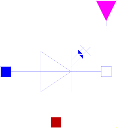 Model Modelica.Electrical.Analog.Ideal.IdealGTOThyristor
This is an ideal GTO thyristor or switching transistor, for details see partial model IdealSemiconductor
The GTO thyristor is conducting if voltage > Vknee AND fire = true.
Otherwise, the GTO thyristor is locking.
Extends from Modelica.Electrical.Analog.Interfaces.IdealSemiconductor (Ideal semiconductor).
| Type | Name | Default | Description |
|---|---|---|---|
Resistance | Ron | 1e-5 | Forward state-on differential resistance (closed resistance) |
Conductance | Goff | 1e-5 | Backward state-off conductance (opened conductance) |
Voltage | Vknee | 0 | Forward threshold voltage |
Boolean | useHeatPort | false | =true, if heatPort is enabled |
Temperature | T | 293.15 | Fixed device temperature if useHeatPort = false |
| Type | Name | Description |
|---|---|---|
PositivePin | p | Positive electrical pin |
NegativePin | n | Negative electrical pin |
HeatPort_a | heatPort | Conditional heat port |
input BooleanInput | fire |
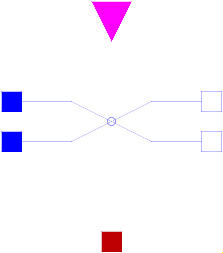
 Model Modelica.Electrical.Analog.Ideal.IdealCommutingSwitch
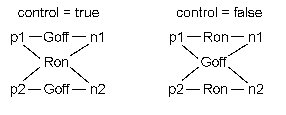
The commuting switch has a positive pin p and two negative pins n1 and n2. The switching behaviour is controlled by the input signal control. If control is true, the pin p is connected with the negative pin n2. Otherwise, the pin p is connected to the negative pin n1.
In order to prevent singularities during switching, the opened
switch has a (very low) conductance Goff
and the closed switch has a (very low) resistance Ron.
The limiting case is also allowed, i.e., the resistance Ron of the
closed switch could be exactly zero and the conductance Goff of the
open switch could be also exactly zero. Note, there are circuits,
where a description with zero Ron or zero Goff is not possible.
Please note:
In case of useHeatPort=true the temperature dependence of the electrical
behavior is not modelled. The parameters are not temperature dependent.
Extends from Modelica.Electrical.Analog.Interfaces.ConditionalHeatPort (Partial model to include a conditional HeatPort in order to describe the power loss via a thermal network).
| Type | Name | Default | Description |
|---|---|---|---|
Resistance | Ron | 1e-5 | Closed switch resistance |
Conductance | Goff | 1e-5 | Opened switch conductance |
Boolean | useHeatPort | false | =true, if heatPort is enabled |
final Temperature | T | 293.15 | Fixed device temperature if useHeatPort = false |
| Type | Name | Description |
|---|---|---|
HeatPort_a | heatPort | Conditional heat port |
PositivePin | p | |
NegativePin | n2 | |
NegativePin | n1 | |
input BooleanInput | control | true => p--n2 connected, false => p--n1 connected |
 Model Modelica.Electrical.Analog.Ideal.IdealIntermediateSwitch
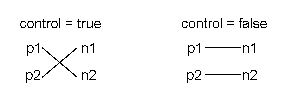
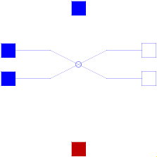
The intermediate switch has four switching contact pins p1, p2, n1, and n2. The switching behaviour is controlled by the input signal control. If control is true, the pin p1 is connected to the pin n2, and the pin p2 is connected to the pin n1. Otherwise,if control is false, the pin p1 is connected to n1, and the pin p2 is connected to n2.
In order to prevent singularities during switching, the opened switch has a (very low) conductance Goff and the closed switch has a (very low) resistance Ron.
The limiting case is also allowed, i.e., the resistance Ron of the closed switch could be exactly zero and the conductance Goff of the open switch could be also exactly zero. Note, there are circuits, where a description with zero Ron or zero Goff is not possible.
Please note: In case of useHeatPort=true the temperature dependence of the electrical behavior is not modelled. The parameters are not temperature dependent.
Extends from Modelica.Electrical.Analog.Interfaces.ConditionalHeatPort (Partial model to include a conditional HeatPort in order to describe the power loss via a thermal network).
| Type | Name | Default | Description |
|---|---|---|---|
Resistance | Ron | 1e-5 | Closed switch resistance |
Conductance | Goff | 1e-5 | Opened switch conductance |
Boolean | useHeatPort | false | =true, if heatPort is enabled |
final Temperature | T | 293.15 | Fixed device temperature if useHeatPort = false |
| Type | Name | Description |
|---|---|---|
HeatPort_a | heatPort | Conditional heat port |
PositivePin | p1 | |
PositivePin | p2 | |
NegativePin | n1 | |
NegativePin | n2 | |
input BooleanInput | control | true => p1--n2, p2--n1 connected, otherwise p1--n1, p2--n2 connected |
 Model Modelica.Electrical.Analog.Ideal.ControlledIdealCommutingSwitch
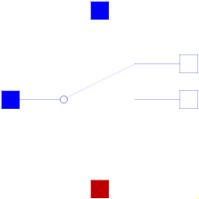
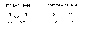
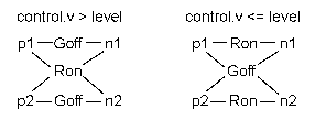
The commuting switch has a positive pin p and two negative pins n1 and n2. The switching behaviour is controlled by the control pin. If its voltage exceeds the value of the parameter level, the pin p is connected with the negative pin n2. Otherwise, the pin p is connected the negative pin n1.
In order to prevent singularities during switching, the opened
switch has a (very low) conductance Goff
and the closed switch has a (very low) resistance Ron.
The limiting case is also allowed, i.e., the resistance Ron of the
closed switch could be exactly zero and the conductance Goff of the
open switch could be also exactly zero. Note, there are circuits,
where a description with zero Ron or zero Goff is not possible.
Please note:
In case of useHeatPort=true the temperature dependence of the electrical
behavior is not modelled. The parameters are not temperature dependent.
Extends from Modelica.Electrical.Analog.Interfaces.ConditionalHeatPort (Partial model to include a conditional HeatPort in order to describe the power loss via a thermal network).
| Type | Name | Default | Description |
|---|---|---|---|
Voltage | level | 0.5 | Switch level |
Resistance | Ron | 1e-5 | Closed switch resistance |
Conductance | Goff | 1e-5 | Opened switch conductance |
Boolean | useHeatPort | false | =true, if heatPort is enabled |
final Temperature | T | 293.15 | Fixed device temperature if useHeatPort = false |
| Type | Name | Description |
|---|---|---|
HeatPort_a | heatPort | Conditional heat port |
PositivePin | p | |
NegativePin | n2 | |
NegativePin | n1 | |
Pin | control | Control pin: if control.v > level p--n2 connected, otherwise p--n1 connected |
 Model Modelica.Electrical.Analog.Ideal.ControlledIdealIntermediateSwitch
The intermediate switch has four switching contact pins p1, p2, n1, and n2. The switching behaviour is controlled by the control pin. If its voltage exceeds the value of the parameter level, the pin p1 is connected to pin n2, and the pin p2 is connected to the pin n1. Otherwise, the pin p1 is connected to the pin n1, and the pin p2 is connected to the pin n2.
In order to prevent singularities during switching, the opened switch has a (very low) conductance Goff and the closed switch has a (very low) resistance Ron.
The limiting case is also allowed, i.e., the resistance Ron of the closed switch could be exactly zero and the conductance Goff of the open switch could be also exactly zero. Note, there are circuits, where a description with zero Ron or zero Goff is not possible.
Please note: In case of useHeatPort=true the temperature dependence of the electrical behavior is not modelled. The parameters are not temperature dependent.
Extends from Modelica.Electrical.Analog.Interfaces.ConditionalHeatPort (Partial model to include a conditional HeatPort in order to describe the power loss via a thermal network).
| Type | Name | Default | Description |
|---|---|---|---|
Voltage | level | 0.5 | Switch level |
Resistance | Ron | 1e-5 | Closed switch resistance |
Conductance | Goff | 1e-5 | Opened switch conductance |
Boolean | useHeatPort | false | =true, if heatPort is enabled |
final Temperature | T | 293.15 | Fixed device temperature if useHeatPort = false |
| Type | Name | Description |
|---|---|---|
HeatPort_a | heatPort | Conditional heat port |
PositivePin | p1 | |
PositivePin | p2 | |
NegativePin | n1 | |
NegativePin | n2 | |
Pin | control | Control pin: if control.v > level p1--n2, p2--n1 connected, otherwise p1--n1, p2--n2 connected |
 Model Modelica.Electrical.Analog.Ideal.IdealOpAmp
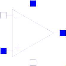
The ideal OpAmp is a two-port. The left port is fixed to v1=0 and i1=0 (nullator). At the right port both any voltage v2 and any current i2 are possible (norator).
| Type | Name | Description |
|---|---|---|
PositivePin | p1 | Positive pin of the left port |
NegativePin | n1 | Negative pin of the left port |
PositivePin | p2 | Positive pin of the right port |
NegativePin | n2 | Negative pin of the right port |
 Model Modelica.Electrical.Analog.Ideal.IdealOpAmp3Pin
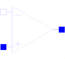
The ideal OpAmp with three pins is of exactly the same behaviour as the ideal OpAmp with four pins. Only the negative output pin is left out. Both the input voltage and current are fixed to zero (nullator). At the output pin both any voltage v2 and any current i2 are possible.
| Type | Name | Description |
|---|---|---|
PositivePin | in_p | Positive pin of the input port |
NegativePin | in_n | Negative pin of the input port |
PositivePin | out | Output pin |
 Model Modelica.Electrical.Analog.Ideal.IdealOpAmpLimited
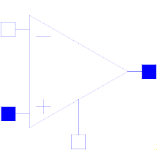
The ideal OpAmp with limitation behaves like an ideal OpAmp without limitation, if the output voltage is within the limits VMin and VMax. In this case the input voltage vin = in_p.v - in_n.v is zero. If the input voltage vin less than 0, the output voltage is out.v = VMin. If the input voltage is vin larger than 0, the output voltage is out.v = VMax.
| Type | Name | Description |
|---|---|---|
PositivePin | in_p | Positive pin of the input port |
NegativePin | in_n | Negative pin of the input port |
PositivePin | out | Output pin |
PositivePin | VMax | Positive output voltage limitation |
NegativePin | VMin | Negative output voltage limitation |
 Model Modelica.Electrical.Analog.Ideal.IdealizedOpAmpLimted
Idealized operational amplifier with saturation:
Supply voltage is either defined by parameter Vps and Vns or by (optional) pins s_p and s_n.
In the first case the necessary power is drawn from an implicit internal supply, in the second case from the external supply.
| Type | Name | Default | Description |
|---|---|---|---|
Real | V0 | 15000 | No-load amplification |
Boolean | useSupply | false | Use supply pins (otherwise constant supply) |
Voltage | Vps | 15 | Positive supply voltage |
Voltage | Vns | -15 | Negative supply voltage |
Boolean | strict | true | = true, if strict limits with noEvent(..) |
LimiterHomotopy | homotopyType | Modelica.Blocks.Types.LimiterHomotopy.Linear | Simplified model for homotopy-based initialization |
| Type | Name | Description |
|---|---|---|
PositivePin | in_p | Positive pin of the input port |
NegativePin | in_n | Negative pin of the input port |
PositivePin | out | Pin of the output port |
PositivePin | s_p | Optional positive supply pin |
NegativePin | s_n | Optional negative supply pin |
The ideal transformer is a two-port circuit element;
in case of Boolean parameter considerMagnetization = false it is characterized by the following equations:
 i2 = -i1*n;
 v2 =  v1/n;
where n is a real number called the turns ratio.
Due to this equations, also DC voltages and currents are transformed - which is not the case for technical transformers.
In case of Boolean parameter considerMagnetization = true it is characterized by the following equations:
 im1  = i1 + i2/n "Magnetizing current w.r.t. primary side";
 psim1= Lm1*im1   "Magnetic flux w.r.t. primary side";
 v1 = der(psim1)  "Primary voltage";
 v2 = v1/n        "Secondary voltage";
where Lm denotes the magnetizing inductance.
Due to this equations, the DC offset of secondary voltages and currents decrement according to the time constant defined by the connected circuit.
Taking primary L1sigma and secondary L2ssigma leakage inductances into account,
compared with the basic transformer
the following parameter conversion can be applied (which leads to identical results):
 L1 = L1sigma + M*n "Primary inductance at secondary no-load";
 L2 = L2sigma + M/n "Secondary inductance at primary no-load";
  M  = Lm1/n         "Mutual inductance";
For the backward conversion, one has to decide about the partitioning of the leakage to primary and secondary side.
Extends from Modelica.Electrical.Analog.Interfaces.TwoPort (Component with two electrical ports, including current).
| Type | Name | Default | Description |
|---|---|---|---|
Real | n | Turns ratio primary:secondary voltage | |
Boolean | considerMagnetization | false | Choice of considering magnetization |
Inductance | Lm1 | Magnetization inductance w.r.t. primary side |
| Type | Name | Description |
|---|---|---|
PositivePin | p1 | Positive electrical pin of port 1 |
NegativePin | n1 | Negative electrical pin of port 1 |
PositivePin | p2 | Positive electrical pin of port 2 |
NegativePin | n2 | Negative electrical pin of port 2 |
 Model Modelica.Electrical.Analog.Ideal.IdealGyrator
A gyrator is an ideal two-port element defined by the following equations:
    i1 =  G * v2

    i2 = -G * v1
where the constant G is called the gyration conductance.
Extends from Modelica.Electrical.Analog.Interfaces.TwoPort (Component with two electrical ports, including current).
| Type | Name | Default | Description |
|---|---|---|---|
Conductance | G | Gyration conductance |
| Type | Name | Description |
|---|---|---|
PositivePin | p1 | Positive electrical pin of port 1 |
NegativePin | n1 | Negative electrical pin of port 1 |
PositivePin | p2 | Positive electrical pin of port 2 |
NegativePin | n2 | Negative electrical pin of port 2 |
 Model Modelica.Electrical.Analog.Ideal.Idle
The model Idle is a simple idle running branch. That means between both pins no current is running. This ideal device is of no influence on the circuit. Therefore, it can be neglected in each case. For purposes of completeness this component is part of the MSL, as an opposite of the short cut.
Extends from Modelica.Electrical.Analog.Interfaces.OnePort (Component with two electrical pins p and n and current i from p to n).
| Type | Name | Description |
|---|---|---|
PositivePin | p | Positive electrical pin |
NegativePin | n | Negative electrical pin |
 Model Modelica.Electrical.Analog.Ideal.Short
The model Short is a simple short cut branch. That means the voltage drop between both pins is zero. This device could be neglected if both pins are combined to one node. Besides connecting the nodes of both pins this device has no further function.
Extends from Modelica.Electrical.Analog.Interfaces.OnePort (Component with two electrical pins p and n and current i from p to n).
| Type | Name | Description |
|---|---|---|
PositivePin | p | Positive electrical pin |
NegativePin | n | Negative electrical pin |
 Model Modelica.Electrical.Analog.Ideal.IdealOpeningSwitch
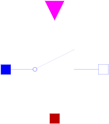
The switching behaviour of the ideal opening switch is controlled by the input signal control: off = control.
For further details, see partial model IdealSwitch.
Extends from Modelica.Electrical.Analog.Interfaces.IdealSwitch (Ideal electrical switch).
| Type | Name | Default | Description |
|---|---|---|---|
Resistance | Ron | 1e-5 | Closed switch resistance |
Conductance | Goff | 1e-5 | Opened switch conductance |
Boolean | useHeatPort | false | =true, if heatPort is enabled |
final Temperature | T | 293.15 | Fixed device temperature if useHeatPort = false |
| Type | Name | Description |
|---|---|---|
PositivePin | p | Positive electrical pin |
NegativePin | n | Negative electrical pin |
HeatPort_a | heatPort | Conditional heat port |
input BooleanInput | control | true => switch open, false => p--n connected |
 Model Modelica.Electrical.Analog.Ideal.IdealClosingSwitch
The switching behaviour of the ideal closing switch is controlled by the input signal control: off = not control.
For further details, see partial model IdealSwitch.
Extends from Modelica.Electrical.Analog.Interfaces.IdealSwitch (Ideal electrical switch).
| Type | Name | Default | Description |
|---|---|---|---|
Resistance | Ron | 1e-5 | Closed switch resistance |
Conductance | Goff | 1e-5 | Opened switch conductance |
Boolean | useHeatPort | false | =true, if heatPort is enabled |
final Temperature | T | 293.15 | Fixed device temperature if useHeatPort = false |
| Type | Name | Description |
|---|---|---|
PositivePin | p | Positive electrical pin |
NegativePin | n | Negative electrical pin |
HeatPort_a | heatPort | Conditional heat port |
input BooleanInput | control | true => p--n connected, false => switch open |
 Model Modelica.Electrical.Analog.Ideal.ControlledIdealOpeningSwitch
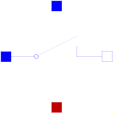
The switching behaviour of the controlled ideal opening switch is controlled by the control pin: off = control.v > level
For further details, see partial model IdealSwitch.
Extends from Modelica.Electrical.Analog.Interfaces.IdealSwitch (Ideal electrical switch).
| Type | Name | Default | Description |
|---|---|---|---|
Voltage | level | 0.5 | Switch level |
Resistance | Ron | 1e-5 | Closed switch resistance |
Conductance | Goff | 1e-5 | Opened switch conductance |
Boolean | useHeatPort | false | =true, if heatPort is enabled |
final Temperature | T | 293.15 | Fixed device temperature if useHeatPort = false |
| Type | Name | Description |
|---|---|---|
PositivePin | p | Positive electrical pin |
NegativePin | n | Negative electrical pin |
HeatPort_a | heatPort | Conditional heat port |
Pin | control | Control pin: control.v > level switch open, otherwise p--n connected |
 Model Modelica.Electrical.Analog.Ideal.ControlledIdealClosingSwitch
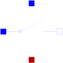
The switching behaviour of the controlled ideal closing switch is controlled by the control pin: off = control.v < level
For further details, see partial model IdealSwitch.
Extends from Modelica.Electrical.Analog.Interfaces.IdealSwitch (Ideal electrical switch).
| Type | Name | Default | Description |
|---|---|---|---|
Voltage | level | 0.5 | Switch level |
Resistance | Ron | 1e-5 | Closed switch resistance |
Conductance | Goff | 1e-5 | Opened switch conductance |
Boolean | useHeatPort | false | =true, if heatPort is enabled |
final Temperature | T | 293.15 | Fixed device temperature if useHeatPort = false |
| Type | Name | Description |
|---|---|---|
PositivePin | p | Positive electrical pin |
NegativePin | n | Negative electrical pin |
HeatPort_a | heatPort | Conditional heat port |
Pin | control | Control pin: control.v > level switch closed, otherwise switch open |
 Model Modelica.Electrical.Analog.Ideal.OpenerWithArc
This model is an extension to the IdealOpeningSwitch.
For details of the arc effect, see partial model IdealSwitchWithArc.
Extends from Modelica.Electrical.Analog.Interfaces.IdealSwitchWithArc (Ideal switch with simple arc model).
| Type | Name | Default | Description |
|---|---|---|---|
Resistance | Ron | 1e-5 | Closed switch resistance |
Conductance | Goff | 1e-5 | Opened switch conductance |
Voltage | V0 | Initial arc voltage | |
VoltageSlope | dVdt | Arc voltage slope | |
Voltage | Vmax | Max. arc voltage | |
Boolean | useHeatPort | false | =true, if heatPort is enabled |
final Temperature | T | 293.15 | Fixed device temperature if useHeatPort = false |
| Type | Name | Description |
|---|---|---|
PositivePin | p | Positive electrical pin |
NegativePin | n | Negative electrical pin |
HeatPort_a | heatPort | Conditional heat port |
input BooleanInput | control | false => p--n connected, true => switch open |
 Model Modelica.Electrical.Analog.Ideal.CloserWithArc
This model is an extension to the IdealClosingSwitch.
For details of the arc effect, see partial model IdealSwitchWithArc.
Extends from Modelica.Electrical.Analog.Interfaces.IdealSwitchWithArc (Ideal switch with simple arc model).
| Type | Name | Default | Description |
|---|---|---|---|
Resistance | Ron | 1e-5 | Closed switch resistance |
Conductance | Goff | 1e-5 | Opened switch conductance |
Voltage | V0 | Initial arc voltage | |
VoltageSlope | dVdt | Arc voltage slope | |
Voltage | Vmax | Max. arc voltage | |
Boolean | useHeatPort | false | =true, if heatPort is enabled |
final Temperature | T | 293.15 | Fixed device temperature if useHeatPort = false |
| Type | Name | Description |
|---|---|---|
PositivePin | p | Positive electrical pin |
NegativePin | n | Negative electrical pin |
HeatPort_a | heatPort | Conditional heat port |
input BooleanInput | control | true => p--n connected, false => switch open |
 Model Modelica.Electrical.Analog.Ideal.ControlledOpenerWithArc
This model is an extension to the ControlledIdealOpeningSwitch.
For details of the arc effect, see partial model IdealSwitchWithArc.
Extends from Modelica.Electrical.Analog.Interfaces.IdealSwitchWithArc (Ideal switch with simple arc model).
| Type | Name | Default | Description |
|---|---|---|---|
Voltage | level | 0.5 | Switch level |
Resistance | Ron | 1e-5 | Closed switch resistance |
Conductance | Goff | 1e-5 | Opened switch conductance |
Voltage | V0 | Initial arc voltage | |
VoltageSlope | dVdt | Arc voltage slope | |
Voltage | Vmax | Max. arc voltage | |
Boolean | useHeatPort | false | =true, if heatPort is enabled |
final Temperature | T | 293.15 | Fixed device temperature if useHeatPort = false |
| Type | Name | Description |
|---|---|---|
PositivePin | p | Positive electrical pin |
NegativePin | n | Negative electrical pin |
HeatPort_a | heatPort | Conditional heat port |
Pin | control | Control pin: control.v > level switch open, otherwise p--n connected |
 Model Modelica.Electrical.Analog.Ideal.ControlledCloserWithArc
This model is an extension to the ControlledIdealClosingSwitch.
For details of the arc effect, see partial model IdealSwitchWithArc.
Extends from Modelica.Electrical.Analog.Interfaces.IdealSwitchWithArc (Ideal switch with simple arc model).
| Type | Name | Default | Description |
|---|---|---|---|
Voltage | level | 0.5 | Switch level |
Resistance | Ron | 1e-5 | Closed switch resistance |
Conductance | Goff | 1e-5 | Opened switch conductance |
Voltage | V0 | Initial arc voltage | |
VoltageSlope | dVdt | Arc voltage slope | |
Voltage | Vmax | Max. arc voltage | |
Boolean | useHeatPort | false | =true, if heatPort is enabled |
final Temperature | T | 293.15 | Fixed device temperature if useHeatPort = false |
| Type | Name | Description |
|---|---|---|
PositivePin | p | Positive electrical pin |
NegativePin | n | Negative electrical pin |
HeatPort_a | heatPort | Conditional heat port |
Pin | control | Control pin: control.v > level switch closed, otherwise switch open |
 Model Modelica.Electrical.Analog.Ideal.IdealTriac
This is an ideal triac model based on an ideal thyristor model.
Two ideal thyristors (Modelica.Electrical.Analog.Ideal.IdealThyristor) are contrarily connected in parallel and additionally eliminated interference with a resistor (Rdis=100) and a capacitor (Cdis=0.005), which are connected in series.
The electrical component triac (TRIode Alternating Current switch) is, due to whose complex structure, a multifunctional applicable construction unit. The application area of this element is the manipulation of alternating current signals in frequency, voltage and/or current and also general blocking or filtering. However, compared to a thyristor the triac is only applied for substantial lesser currents, what is justified by whose sensitive structure. Generally one is limited to maximal voltages from 800 volt and currents from 40 ampere. For comparison maximal voltages of a thyristor are 8.000 volt and currents 5.000 ampere.
Structure and functionality:
Functionality of a triac is in principle the same like functionality of a thyristor, even connecting through of current starting from a certain voltage (knee voltage), but only if the current at anode and cathode is caused by a impulse current in the gate electrode. In case of the triac this process is also possible with reverse polarity, wherefore it is possible to control both half-waves of alternating currents. By means of gate electrodes, which are connected in a triac and why only one gate electrode is necessary, the point of time can be determined, at which the triac lets the alternating current signal pass. Thereby it is possible to affect the phase, at which the alternating current signal is cut. One speaks also of phase-angle control. Also depending on doping and specific structure knee voltage and maximal current carrying are alterable.
Characteristics:
Applications:
As an additional information: this model is based on the Modelica.Electrical.Analog.Ideal.IdealThyristor.
| Type | Name | Default | Description |
|---|---|---|---|
Resistance | Ron | 1e-5 | Closed triac resistance |
Conductance | Goff | 1e-5 | Opened triac conductance |
Voltage | Vknee | 0.8 | Threshold voltage for positive and negative phase |
Resistance | Rdis | 100 | Resistance of disturbance elimination |
Capacitance | Cdis | 0.005 | Capacity of disturbance elimination |
| Type | Name | Description |
|---|---|---|
input BooleanInput | fire1 | Gate |
NegativePin | n | Cathode |
PositivePin | p | Anode |
 Model Modelica.Electrical.Analog.Ideal.AD_Converter
Simple analog to digital converter with a variable resolution of n bits.
It converts the input voltage ppin.v-npin.v to an n-vector of type Logic
(9-valued logic according to IEEE 1164 STD_ULOGIC). The input resistance between positive and negative pin is determined by Rin.
Further effects (like input capacities) have to be modeled outside the converter, since this should be a general model.
The input signal range (VRefLo,VRefHi) is divided into 2^n-1 equally spaced stages of length Vlsb:=(VRefHi-VRefLo)/(2^n-1).
The output signal is the binary code of k as long as the input voltage takes values in the k-th stage, namely in the range from
Vlsb*(k-0.5) to m*(k+0.5). This is called mid-tread operation. Additionally the output can only change
its value if the trigger signal trig of type Logic changes to '1' (forced or weak).
The output vector is a 'little-endian'. i.e., that the first bit y[1] is the least significant one (LSB).
This is an abstract model of an ADC. Therefore, it can not cover the dynamic behaviour of the converter. Hence the output will change instantaneously when the trigger signal rises.
| Type | Name | Default | Description |
|---|---|---|---|
Integer | N | Resolution in bits - output signal width | |
Voltage | VRefHigh | High reference voltage | |
Voltage | VRefLow | Low reference voltage | |
Resistance | Rin | Input resistance |
| Type | Name | Description |
|---|---|---|
PositivePin | p | Positive electrical pin (input) |
NegativePin | n | Negative electrical pin (input) |
output DigitalOutput | y[N] | Digital output |
input DigitalInput | trig | Trigger input |
 Model Modelica.Electrical.Analog.Ideal.DA_Converter
Simple digital to analog converter with a variable input signal width of N bits. The input signal is an N-vector of type Logic (9-valued logic according to IEEE 1164 STD_ULOGIC). The output voltage of value y is generated by an ideal voltage source. The output can only change if the trigger signal trig of type Logic changes to '1' (forced or weak). In this case, the output voltage is calculated in the following way:
       N
  y = SUM ( x[i]*2^(i-1) )*Vref/(2^N-1),
      i=1
where x[i], i=1,...,N is 1 or 0. and Vref is the reference value. Therefore, the first bit in the input vector x[1] is the least significant one (LSB) and x[N] is the most significant bit (MSB).
This is an abstract model of a DAC. Hence, it can not cover the dynamic behaviour of the converter. Therefore the output will change instantaneously when the trigger signal rises.
| Type | Name | Default | Description |
|---|---|---|---|
Integer | N | Resolution - input signal width | |
Voltage | Vref | Reference voltage |
| Type | Name | Description |
|---|---|---|
input DigitalInput | trig | Trigger input |
input DigitalInput | x[N] | Digital input |
PositivePin | p | Positive electrical pin (output) |
NegativePin | n | Negative electrical pin (output) |