 Package Modelica.Electrical.PowerConverters.ACDC.Control
Control components for rectifiers
 Package Modelica.Electrical.PowerConverters.ACDC.Control
A generic controller with signal input and 2*m firing signals is provided in
Signal2mPulse,
where m is the arbitrary number of phases.
Additional topology specific controllers with electrical connectors are also included.
Each controller is equipped with an optional filter to filter the input voltages. By default the filter is enabled.
Such filter is needed if the electrical grid includes a significant voltage drop across the grid impedance distorting the input voltage wave form of the rectifier. The filter included in the PowerConverters library is first order filter with additional compensation of the filter specific phase lag. However, it important to note that the transients of the filters may cause some initial effects which deteriorate after certain periods.
The topology specific controllers allow enabling and disabling of the firing signals. The internal enabling signal of the controllers is either derived from the parameter constantEnable,
if useConstantEnable = true. For if useConstantEnable = false the internal
enabling signal is taken from the optional signal input enable.
Extends from Modelica.Icons.Package (Icon for standard packages).
| Name | Description |
|---|---|
Filter | PT1 + all-pass filter |
Signal2mPulse | Generic control of 2*m pulse rectifiers |
VoltageBridge2mPulse | Control of 2*m pulse bridge rectifier |
VoltageBridge2Pulse | Control of 2 pulse bridge rectifier |
VoltageCenterTap2mPulse | Control of 2*m pulse center tap rectifier |
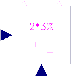 Block Modelica.Electrical.PowerConverters.ACDC.Control.Signal2mPulse
General information about controllers is summarized in Control.
Extends from Modelica.Electrical.PowerConverters.Icons.Control (Control icon).
| Type | Name | Default | Description |
|---|---|---|---|
Integer | m | 3 | Number of phases |
Boolean | useConstantFiringAngle | true | Use constant firing angle instead of signal input |
Angle | constantFiringAngle | 0 | Firing angle |
Boolean | useFilter | true | Enable use of filter |
Frequency | f | 50 | Frequency |
Frequency | fCut | 2 * f | Cut off frequency of filter |
Voltage | vStart[m] | zeros(m) | Start voltage of filter output |
Angle | firingAngleMax | Modelica.Constants.pi | Maximum firing angle |
| Type | Name | Description |
|---|---|---|
input RealInput | firingAngle | Firing angle (rad) |
output BooleanOutput | fire_p[m] | |
output BooleanOutput | fire_n[m] | |
input RealInput | v[m] | Voltages |
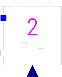 Model Modelica.Electrical.PowerConverters.ACDC.Control.VoltageBridge2Pulse
General information about controllers is summarized in Control.
This model provides two firing signal for Graetz bridge thyristor and half bridge rectifiers. The boolean
signal fire_p is assigned to the thyristors connected with the positive DC output pin.
The boolean
signal fire_n is assigned to the thyristors connected with the negative DC output pin.
Extends from Modelica.Electrical.PowerConverters.Icons.Control (Control icon).
| Type | Name | Default | Description |
|---|---|---|---|
Frequency | f | 50 | Frequency |
Boolean | useConstantFiringAngle | true | Use constant firing angle instead of signal input |
Angle | constantFiringAngle | 0 | Firing angle |
Angle | firingAngleMax | Modelica.Constants.pi | Maximum firing angle |
Boolean | useFilter | true | Enable use of filter |
Frequency | fCut | 2 * f | Cut off frequency of filter |
Voltage | vStart | 0 | Start voltage of filter output |
| Type | Name | Description |
|---|---|---|
input RealInput | firingAngle | Firing angle (rad) |
PositivePin | ac_p | |
NegativePin | ac_n | |
output BooleanOutput | fire_p | |
output BooleanOutput | fire_n |
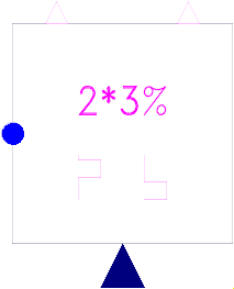 Model Modelica.Electrical.PowerConverters.ACDC.Control.VoltageBridge2mPulse
General information about controllers is summarized in Control.
Half of the semiconductors of the 2*m pulse bridge rectifier are connected with the positive DC output pin (firing signal fire_p). The other half of the semiconductors is connected with the negative DC output pin (firing signal fire_n). Parameter m indicates the number of phases.
Extends from Modelica.Electrical.PowerConverters.Icons.Control (Control icon).
| Type | Name | Default | Description |
|---|---|---|---|
Integer | m | 3 | Number of phases |
Frequency | f | 50 | Frequency |
Boolean | useConstantFiringAngle | true | Use constant firing angle instead of signal input |
Angle | constantFiringAngle | 0 | Firing angle |
Angle | firingAngleMax | Modelica.Constants.pi | Maximum firing angle |
Boolean | useFilter | true | Enable use of filter |
Frequency | fCut | 2 * f | Cut off frequency of filter |
Voltage | vStart[m] | zeros(m) | Start voltage of filter output |
| Type | Name | Description |
|---|---|---|
input RealInput | firingAngle | Firing angle (rad) |
PositivePlug | ac | |
output BooleanOutput | fire_p[m] | |
output BooleanOutput | fire_n[m] |
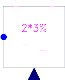 Model Modelica.Electrical.PowerConverters.ACDC.Control.VoltageCenterTap2mPulse
General information about controllers is summarized in Control.
Extends from Modelica.Electrical.PowerConverters.Icons.Control (Control icon).
| Type | Name | Default | Description |
|---|---|---|---|
Integer | m | 3 | Number of phases |
Frequency | f | 50 | Frequency |
Boolean | useConstantFiringAngle | true | Use constant firing angle instead of signal input |
Angle | constantFiringAngle | 0 | Firing angle |
Angle | firingAngleMax | Modelica.Constants.pi | Maximum firing angle |
Boolean | useFilter | true | Enable use of filter |
Frequency | fCut | 2 * f | Cut off frequency of filter |
Voltage | vStart[m] | zeros(m) | Start voltage of filter output |
| Type | Name | Description |
|---|---|---|
input RealInput | firingAngle | Firing angle (rad) |
PositivePlug | ac | |
output BooleanOutput | fire_p[m] | |
output BooleanOutput | fire_n[m] |
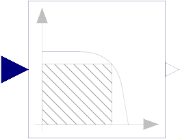 Block Modelica.Electrical.PowerConverters.ACDC.Control.Filter
First order filter with cut-off frequency fCut. The phase shift of the filter is compensated by a series of two first order all-pass filters tuned on supply frequency f.
Extends from Modelica.Blocks.Interfaces.SISO (Single Input Single Output continuous control block).
| Type | Name | Default | Description |
|---|---|---|---|
Frequency | f | 50 | Mains Frequency |
Frequency | fCut | 2 * f | Cut off frequency |
final Integer | na | 2 | Count of 1st order all-pass |
final Frequency | fa | f / tan(pi / na - atan(f / fCut) / (2 * na)) | |
Real | yStart | 0 | Start value of output |
| Type | Name | Description |
|---|---|---|
input RealInput | u | Connector of Real input signal |
output RealOutput | y | Connector of Real output signal |