From the ribbon, in the the Files tool group, click or,
from the menu bar, select File > New.
A new modeling window opens for you to create a model.
Files for This Tutorial
SineIntegral.scm
A finished version of the models you build in the tutorials along with any files
required to complete the tutorials are available at this location:
<installation_directory>/tutorial_models/.
Creating a Diagram
Build a diagram from the blocks located in the palettes of the System
library.
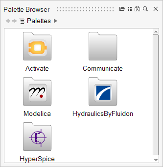
Select View > Palette Browser.
The Palette Browser displays the installed library
palettes.
Double-click Activate > Signal Generators.
The Palette Browser displays the blocks
available in the Signal Generators palette.
Select the SineWaveGenerator block, then drag and drop
it into the modeling window.
The SineWaveGenerator block is the first block in your diagram
assembly.
From the Palette Browser, drag and drop the following
blocks into your diagram:
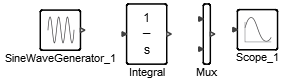
From Activate > Dynamical, drag and drop one Integral block to
the right of the SineWaveGenearator block.
From Activate > Routing, drag and drop one Mux block to the
right of the Integral block.
From Activate > SignalViewers, drag and drop one Scope block to the
right of the Mux block.
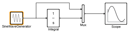
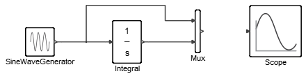
Your block assembly should look something like this:
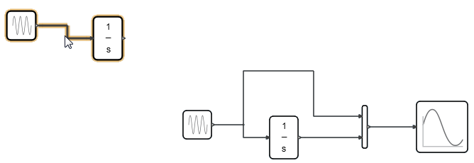
Hover over the output port of the SineWaveGenerator
block until the cursor becomes a pointer-hand, then click:
Click the input port of the Integral block:
A link appears between the blocks:
Tip: To connect the blocks
automatically, hold the Shift
key + click each block. The next available output from the first block
connects to the next available input of the second block. To deselect a
port, press Esc.
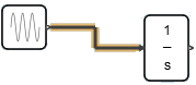
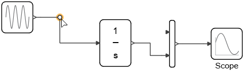
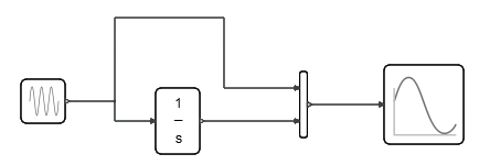
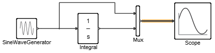
Link the remaining blocks in the diagram as you see in the following figure.
Note the bend in the link between the first two blocks. If your link is
straight, create the bend by selecting the SineWaveGenerator block and moving it
upward so that it is higher than the Integral block.
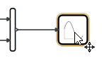
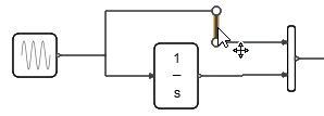
Hold the Alt key and click the
elbow of the link between the SineWaveGenerator and
Integral blocks.
A split is created in the link:
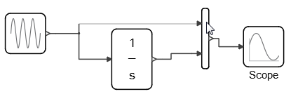
Drag the link to the upper input port of the Mux
block:
Alternatively, click the upper input port of the Mux block to initiate a
link, then click the destination-link elbow to create the split:
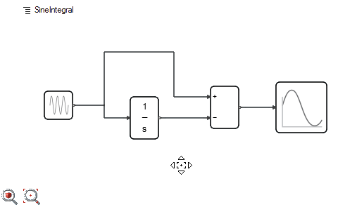
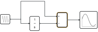
Your completed diagram should look something like this:
On the ribbon, from the Files
tool group, click Save.
In the Save Model As dialog, specify a directory, and
for File name, enter
SineIntegral_practice.
Your diagram is saved as the model file,
SineIntegral_practice.scm.
Adjusting Blocks and Links
Adjust the size of the blocks and position of the links in your diagram.
To better align the link between the Mux and Scope blocks, click and hold the
Scope block, and then move the block down slightly
until the link becomes a straight line.
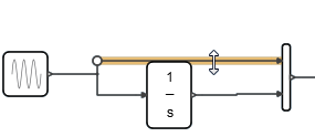
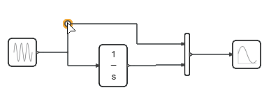
Hover over the link connected to the upper input port of the Mux block until
the link segment is highlighted.
Hold and drag the link segment upward, and then drop the segment at a position
above the Integral block.
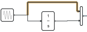
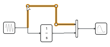
Select the vertical part of the link and move to the left so that it is not too
close to the Mux block.
Click and hold the point you see in the following figure. You can adjust the
link route by moving a point rather than a link segment.
Drag the mouse up and release it when the link route is acceptable.
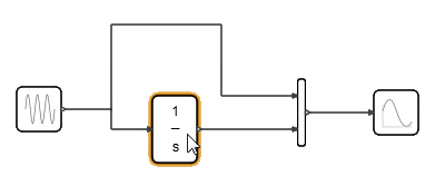
Select the Integral block. Hold and drag your mouse up
slightly to straighten the crooked link between the Integral and Mux
blocks.
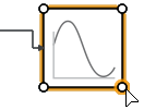
Select the Scope block and hover over one of its
corners.
Control points appear:
To increase the size of the block, drag the control points outward.
Keeping the Scope block selected, move the block up slightly to straighten the
link between the Mux and Scope blocks.
Click File > Save.
Deleting Blocks and Links
Delete and restore blocks and links in your diagram.
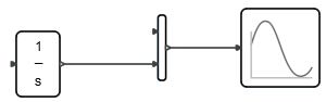
On your model, select the SineWaveGenerator block.
Right-click, and from the context menu, select Delete.
The SineWaveGenerator block and the links associated with it are
removed.
To restore the deleted blocks and links, click Edit > Undo or press Ctrl +
Z.
Select the link connected to the Scope block:
Right-click, and from the context menu, select
Delete.
To restore the deleted link, click Edit > Undo, or press Ctrl +
Z.
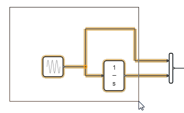
To delete multiple blocks and links at once, you can box-select a section of
the diagram, and then delete and restore the section as above. From the upper
left-hand corner of the diagram, click and drag downward and right to select the
portion of the diagram containing the SineWaveGenerator and Integral
blocks.
Click outside the selecting rectangle to deselect the blocks and links.
Copying Blocks
Duplicate blocks in your diagram with the copy-and-paste or Ctrl key + drag methods.
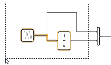
Near the upper right-hand corner of the diagram, click and drag a box downward
from right to left. This selection method is called cross-selecting. Only the
objects inside of the box are selected.
A dashed line appears around the portion of the diagram that is
selected.
In your diagram, cross-select the SineWaveGenerator and
Integral blocks. Right-click the selected box, and
from the context menu, select Copy or press
Ctrl+ C.
To paste the copied blocks and links, right-click outside of the selection, and
from the context menu, select Paste or press
Ctrl+ V.
Duplicates of the selected blocks appear in your diagram.
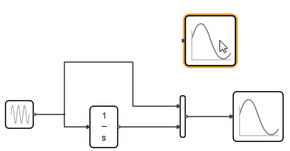
Alternatively, to duplicate a block, select the Scope
block; press and hold the Ctrl
key; drag the selected Scope block to an empty area in
the diagram; release the mouse, and release the Ctrl key.
A duplicate Scope block appears:
Select File > Close. Do not save the changes to the model file.
Flipping and Replacing Blocks
Position objects in your diagram with Flip and Replace options.
Select File > Open SineIntegral_practice.scm.
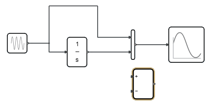
In the Palette Browser,
double-click Activate, double-click
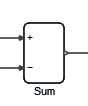
MathOperations, select the Sum
block and drag and drop it into the diagram.
On the Sum block, right-click, and from the context
menu, select Flip.
The block flips horizontally, as if it were mirrored about a vertical
axis across its center.
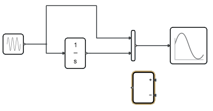
Flip the Sum block again to restore its original
orientation.
To cut the block, right-click the Sum block, select
Cut or press Ctrl + X.
Right-click the Mux block, and from the context menu,
select Paste.
The Mux block is replaced by the Sum block that was cut in the previous
step.
Right-click the Sum block and from the context menu that
appears, select Show Name. If the block is already
showing its label, select Hide Name.
Viewing with Pan, Fit and Zoom Tools
Adjust the view of your model.
At the lower left-hand corner of the modeling window, click the Fit
Selected tool , or press the F key.
The view of the diagram adjusts to fit the modeling window.
Click the Fit to Zoom One tool.
The view of the blocks in the model is adjusted so that they are the
same size as those in the Palette Browser. This is the
default view when a model is initially loaded.
Hold and drag the middle mouse button to pan the diagram and move specific
parts of it into view.
 or,
from the menu bar, select .
or,
from the menu bar, select .


 Tip: To connect the blocks automatically, hold the Shift key + click each block. The next available output from the first block connects to the next available input of the second block. To deselect a port, press Esc.
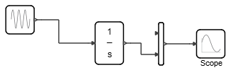
 Alternatively, click the upper input port of the Mux block to initiate a link, then click the destination-link elbow to create the split:
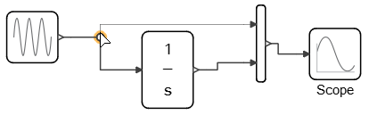 Your completed diagram should look something like this:
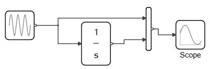

 , or press the F key.
The view of the diagram adjusts to fit the modeling window.
, or press the F key.
The view of the diagram adjusts to fit the modeling window.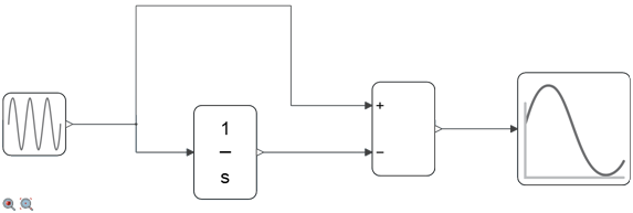
 tool.
The view of the blocks in the model is adjusted so that they are the same size as those in the Palette Browser. This is the default view when a model is initially loaded.
tool.
The view of the blocks in the model is adjusted so that they are the same size as those in the Palette Browser. This is the default view when a model is initially loaded.