Tutorial: Introduction to Modeling with Spice
Learn how to design a Band Pass Filter with components from the Spice block library and simulate the model with the Spice solver.
Files for This Tutorial
SpiceBandPassFilter.scm
Overview of the Band Pass Filter
Band pass filters are widely used in wireless transmitters and receivers to pass and block frequencies within a certain range. The main purpose of the filter is to refine a noisy signal into an ideal signal within a set of frequencies.
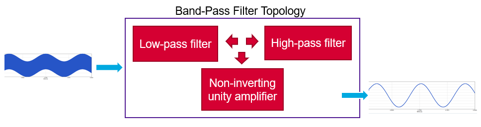
The model that you build for this tutorial includes a low-pass filter (passive) and amplifier. Your goal is to remove the high-frequency signal and keep only frequencies in the pass band. You will set the cut frequency (fc) to 50hz and amplify the signal by 10x.
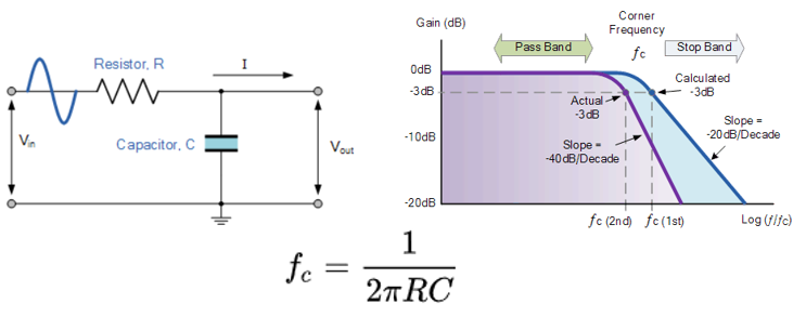
Design the Low Pass Filter
Construct the low-pass filter portion of your band-pass filter model. Include a resistor and capacitor.
-
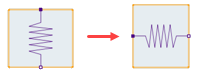
On the ribbon, select the left arrow on the Orient
tool:

The resister rotates to the left:
-
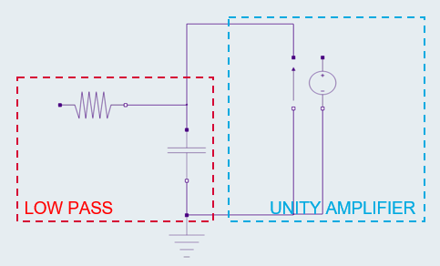
Connect the components as follows:
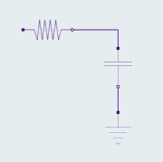
The low-pass filter of the electrical schematic of the BandPassFilter model is complete.
Design the Non-Inverting Unity Amplifier
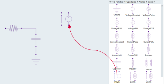
Create a non-inverting unity amplifier with a Voltage Controlled Voltage Source (VCVS).
-
In the Palette Browser, from , drag one VCVS block into the current
diagram and double-click the block.
-
Connect the amplifier to the low-pass filter.
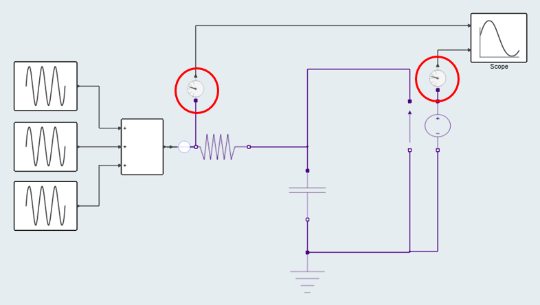
Your model should look something like this: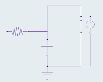
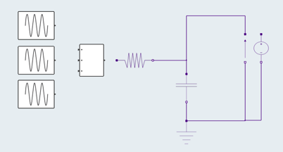
Next define the source for the excitation by combining the three sinusoidal signals at different frequencies.
-
Add the following blocks to your model from the Palette Browser:
- From , drag three SineWaveGenerator blocks into the diagram.
- From , drag one Sum block into the
diagram.Note: Choose the Sum block that has ports on the left side.
-
Double-click the Sum block and define these parameters:
- For Number of inputs, enter 3.
- For each input port, select the '+' operator.
- Keep the default values for all other parameters.
-
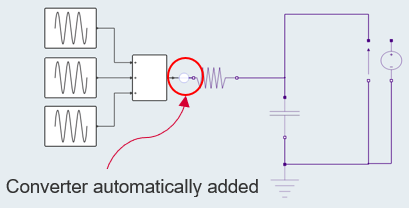
Connect the blocks you just added to the model. Note that the converter is
automatically added between the Sum block and the Resistor.
-
Connect the Scope block to the model. Note that the converters from the model
to the Scope are automatically added to the model.
Simulating the Diagram
-
On the ribbon, select Setup.

-
On the ribbon, select Run.

The Scope block in the model should generate a plot that looks something like this: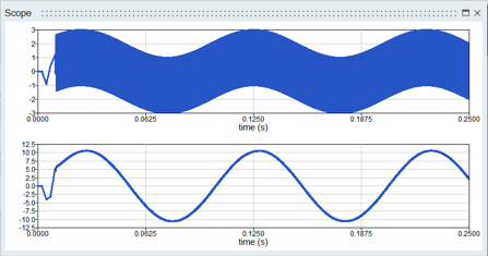
The plot shows that the low-pass filter removed the high-frequency signal and passed only the frequencies that were less than 50 Hz. The signal in the pass band was amplified by 10.