Tutorial: Creating a Modelica Custom Component
Learn the process of customizing a MoCustomComponent block to replace an existing Modelica Standard Library block in a model.
Files for This Tutorial
ActiveRC.scm
Defining the Modelica Custom Component
Define the ports, parameters and simulation function for a MoCustomComponent block.
-
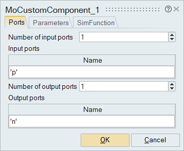
On the block dialog, select the tab, Ports, and enter
the information to define one input and one output port as you see in the
following figure:
 Important: Reviewing the Modelica MO code will help you understand what ports are required for the component.
 -
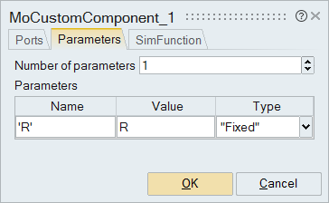
On the block dialog, select the Parameters tab. For
Number of parameters, enter 1. For Name, enter
'R', and for Value, enter
R.
-
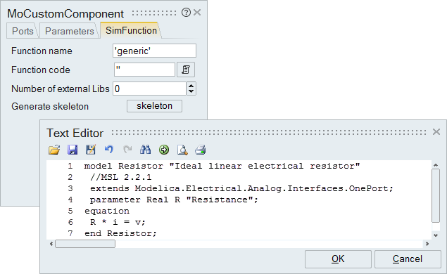
On the SimFunction tab:
- For Function name, enter Resistor.
- Next to the field for the Function code, click
 . In the text editor that opens, copy and paste the following Modelica
code:
. In the text editor that opens, copy and paste the following Modelica
code:model Resistor "Ideal linear electrical resistor" //MSL 2.2.1 extends Modelica.Electrical.Analog.Interfaces.OnePort; parameter Real R "Resistance"; equation R * i = v; end Resistor; - Click OK.
 The Modelica Custom Component block is defined and ready to be connected to the model.
Implementing the Modelica Custom Component
Replace the existing R=1 resistor blocks with the Modelica Custom Component.
-
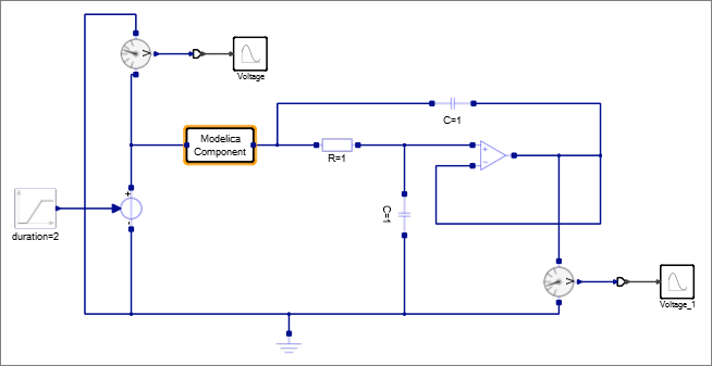
From the model, select and cut the Modelica Component,
select the left resistor, R=1, and paste the Modelica
Component block.
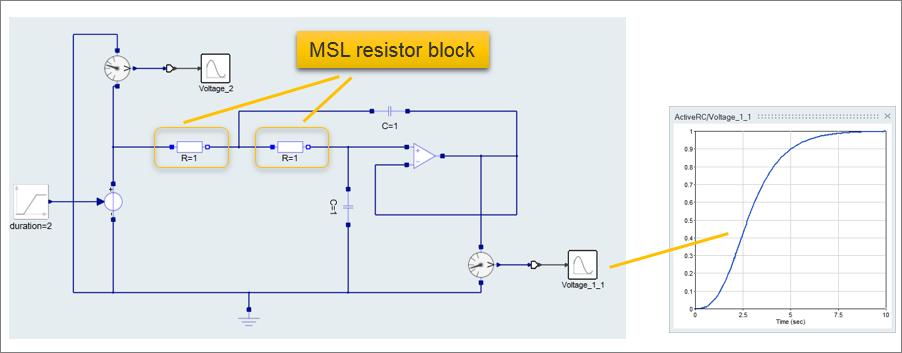
One of the two original resistor blocks is replaced with the Modelica Component. Your model should look something like this:
-
On the ribbon, select the Super Block tool:
 , or right-click and from the context menu, select Super
Block.
The Modelica Component is converted into a super block.
, or right-click and from the context menu, select Super
Block.
The Modelica Component is converted into a super block. -
On the ribbon, from the Mask tool group, click the
Auto Mask tool:
 .
The super block is masked.
.
The super block is masked. -
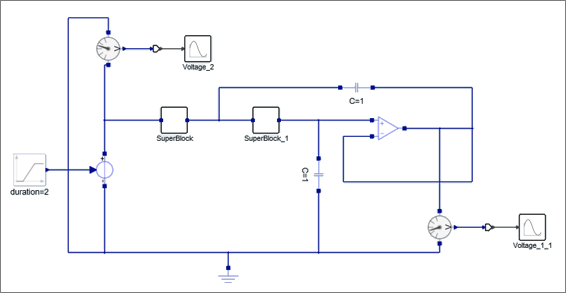
In the diagram, copy the SuperBlock, select the
remaining resistor block, R=1, and paste the
SuperBlock.
The SuperBlock replaces the second resistor block. The model now contains two super blocks: SuperBlock and SuperBlock_1.
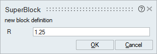
-
In the dialog, for R, enter 1.25.