When solid/fluid domains are in contact, Fluent requires a
component of type Wall defining all the faces that separate components of different type
(fluid/solid). For example, if you have a fluid domain fluid1 and a solid domain solidA that
are in contact, then all the faces that have a cell of fluid1 on one side and a cell of
solidA on the other side have to be in a separate component of type Wall. This component can
be called wall_fluid1_solidA, for example.
This is illustrated with a simple example below: Figure 1.
This model has a fluid and a solid domain that have been named fluid and solid,
respectively. Both domains alone are shown below: Figure 2.
It is noted above that Fluent requires a component of type Wall
defining all the faces that separate components of different type (fluid/solid). If you do
not define such components, they are created automatically when you export
.CAS files. This is the preferred approach as everything is done
automatically for you. However, if you want to generate such components manually, they have
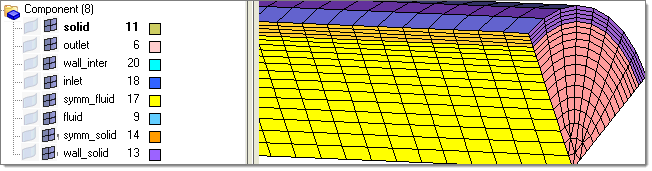
to be created extracting ^faces (use BCs > Faces) from the fluid volume component. In the example above, some elements from
^faces were moved (Mesh > Organize) to symm_fluid, some to inlet, some to outlet and the remaining are those in
contact with the component solid, those are moved to component wall_inter. Figure 3.
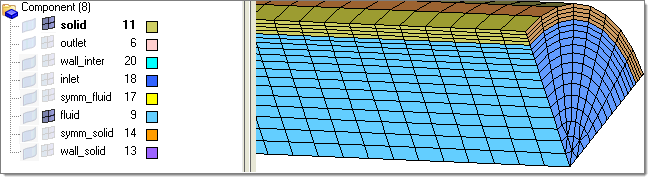
When you extract ^faces from the solid volume component, you move some to symm_solid and
some to wall_solid, but those that are in contact with component fluid are discarded. This
is shown below: Figure 4.
Before exporting a .cas file for Fluent,
make sure that all the volume and surface components that define the CFD model are
displayed, as shown below: Figure 5.
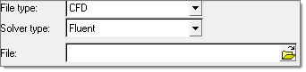
Then, using the Export tab, set the file type field to CFD, select Fluent in the Solver type field and browse to select the file. Figure 6.
Using Fluent-3d, you can import the CFD model created with
Engineering Solutions by using the File > Read > Case option and selecting the .cas file that you saved with
Engineering Solutions. Fluent
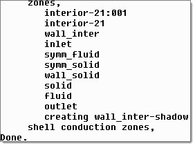
displays the components that are imported, as shown below: Figure 7. Figure 8.
As indicated before, the wall component (wall_inter) separating the volume components is
imported as such and a shadow component is created on the other side wall_inter-shadow. This
is how Fluent handles the interfaces between volume components
of different type (for example solid/fluid). Other than this, you can see that all the
boundary components remain exactly as they were defined.