HM-3200: Tetramesh
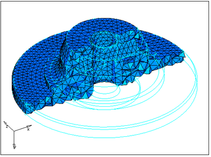
HyperMesh provides two methods for generating a tetrahedral element mesh. The volume tetra mesher works directly with surface or solid geometry to automatically generate a tetrahedral mesh without further interaction from you. Even with complex geometry, this method can often generate a high quality tetra mesh quickly and easily.
The standard tetra mesher requires a surface mesh of tria or quad elements as input, and then provides you with a number of options to control the resulting tetrahedral mesh. This offers a great deal of control over the tetrahedral mesh, and provides the means to generate a tetrahedral mesh for even the most complex models.
You can use the Tetramesh panel to fill an enclosed volume with first or second order tetrahedral elements. A region is considered enclosed if it is entirely bounded by a shell mesh (tria or quad elements), where each element has material on one side and open space on the other.
- Volume tetra mesher
- Standard tetra mesher
- Checking tetra element quality
- Remeshing tetra elements
This exercise uses the housing.hm file, which can be found in the hm.zip file. Copy the file from this directory to your working directory.
Open the Model File
In this step you will open and view the model file, housing.hm.
- Start HyperMesh Desktop.
- From the menu bar, click .
- In the Open Model dialog, open the housing.hm model file.
- Observe the model using the different visual options available in HyperMesh (rotation, zooming, and so on). Only the geometry in the component cover is currently displayed. The file contains two parts defined by a volume of surfaces. The geometry has been cleaned such that surface connectivity is proper and surface edges that would cause sliver elements are suppressed.
Create a Tetra Mesh Using Volume Tetra Mesher
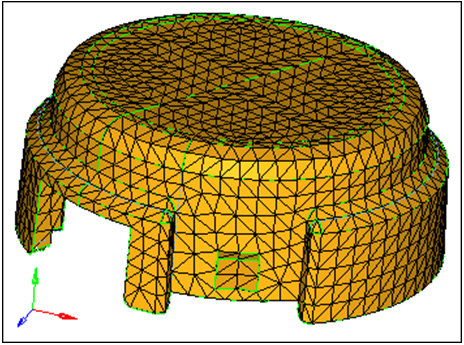
In this step you will use the volume tetra mesher and equilateral triangles to create a tetra mesh for the cover.
Create a Tetra Mesh Using Right Triangles
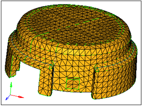
In this step you will use the volume tetra mesher and right triangles to create a tetra mesh for the cover.
You should still be in the Volume tetra subpanel.
Create a Tetra Mesh Along Curved Surfaces
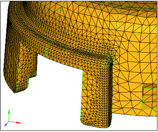
In this step you will use the volume tetra mesher to create a tetra mesh with more elements along curved surfaces.
You should still be in the Volume tetra subpanel.
Use the Volume Tetra Mesher to Create a Tetra Mesh
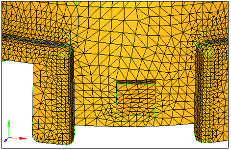
In this step you will use the volume tetra mesher to create a tetra mesh with more elements around small features.
You should still be in the Volume tetra subpanel.
Prepare the Display to Tetra Mesh
In this step you will prepare the display to tetra mesh the hub component using the standard tetra mesher.
Review the Connectivity and Quality of the Mesh
In this optional step, you will review the connectivity and quality of the tria mesh to validate its integrity for the standard tetra mesher.
You will use the Edges and Check Elems panels to make sure that there are no free edges or very small angles in the tria shell mesh.
Use the Standard Tetra Mesher
In this step you will create a tetra mesh for the hub using the standard tetra mesher.
Check Quality of Tetra Elements
In this step you will check the quality of the hub's tetra elements.
Isolate the Element
In this step you will isolate the element with the tetra collapse smaller than 0.2 and find the elements surrounding it.
You should still be in the Check Elements panel.
Remesh Tetra Elements
In this step you will remesh the hub's displayed tetra elements to improve their tetra collapse.
Save Your Work
In this optional step you will save your work.
You have created a tetra mesh for both parts in the model using different tetra meshing procedures. Either method can be used to mesh parts, depending on the needs of the analysis. The tetra remesh function was used in this tutorial to show how to quickly fix the quality of tetra elements.
