OS-T: 2060 Symmetry and Draw Direction Constraints Applied Simultaneously
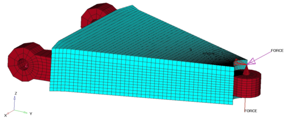
In this tutorial you will perform a topology optimization on an automotive control arm with the simultaneous application of symmetry and draw direction constraints.

Figure 1.
- Objective
- Minimize volume.
- Constraints
- SUBCASE 1: The resultant displacement of the point where loading is applied must be less than 0.05 mm.
- Design Variables
- Element density.
Launch HyperMesh and Set the OptiStruct User Profile
Import the Model
Set Up the Optimization
Define the Symmetry and Draw Direction Manufacturing Constraints
- From Analysis page, click the optimization panel.
- Click the topology panel.
-
Defining minimum member size.
-
Defining the draw direction.
-
Define the symmetry constraint.
- Click return twice to go back to the Analysis page.
Run the Optimization
View the Results
Element density results are output to the carm_draw_symm_complete_des.h3d file from OptiStruct for all iterations. In addition, Displacement and Stress results are output for each subcase for the first and last iterations by default into carm_draw_symm_complete_s#.h3d files, where # specifies the sub case ID.
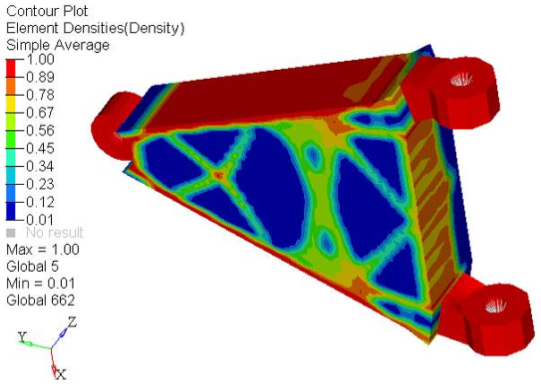
Review the Contour Plot of the Density Results
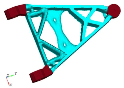
View an Iso Value Plot of Element Densities
- Have most of your elements converged to a density close to 1 or 0?
- If there are many elements with intermediate densities, the DISCRETE parameter may need to be adjusted. The DISCRETE parameter (set in the opti control panel on the Optimization panel) can be used to push elements with intermediate densities toward 1 or 0, so that a more discrete structure is given.
- Is the max= field showing 1.0e+00?
- In this case, it is.
- Has the volume been minimized for the given constraints?
- Have the displacement constraints been met?
 .
. 

 to return to the Design History page, indicating that the
results correspond to optimization iterations.
 to open the
 to open the Iso Value panel.