Tabulated Failure Model /FAIL/TAB1
In Radioss, /FAIL/TAB1 is the most sophisticated failure model for ductile material. The plastic failure strain can be defined as a function of: stress triaxiality, strain rate, Lode angle, element size, temperature, and instability strain.
Damage is accumulated based on user-defined functions. The functionality of this failure model will be described starting with the most basic input to the most complex options.
Plastic Failure Strain

Figure 1. Material Failure Curve Defined using Discrete Points with a Local Maximum
/TABLE/1/4711
failure plastic-strain vs triaxiality
#dimension
         1
#        Triaxiality      Failure_Strain
             -0.7000              0.3386
             -0.6000              0.3068
             -0.5000              0.2794
             -0.4000              0.2558
             -0.3333              0.2419
             -0.3000              0.2355
             -0.2000              0.2180
             -0.1000              0.2029
              0.0000              0.1900
              0.1000              0.1789
              0.2000              0.1693
              0.3000              0.1610
              0.3333              0.1585
              0.4000              0.1539
              0.5000              0.1478
              0.6000              0.1425
              0.7000              0.1380
Strain Rate Dependency
/FAIL/TAB1 can also include the influence of strain rate on material failure. For this case the /TABLE must be defined such that, the first dimension is the function ID for the failure curve and the second dimension is the strain rate where that failure curve is applied.
/TABLE/1/4711
failure plastic-strain vs triaxiality and strain rate
#dimension
         2
#   FCT_ID                   strain_rate
      3000                          1E-4
      3001                           0.1
      3002                           1.0
/FUNCT/3000
failure plastic-strain vs triaxiality
#        Triaxiality      Failure_Strain
             -0.7000              0.3386
             -0.6000              0.3068
             -0.5000              0.2794
             -0.4000              0.2558
             -0.3333              0.2419
             -0.3000              0.2355
             -0.2000              0.2180
             -0.1000              0.2029
              0.0000              0.1900
              0.1000              0.1789
              0.2000              0.1693
              0.3000              0.1610
              0.3333              0.1585
              0.4000              0.1539
              0.5000              0.1478
              0.6000              0.1425
              0.7000              0.1380
/FUNCT/3001
failure plastic-strain vs triaxiality
#        Triaxiality      Failure_Strain
                -0.7             0.27088
                -0.6             0.24544
                -0.5             0.22352
                -0.4             0.20464
             -0.3333            0.19352
                -0.3              0.1884
                -0.2              0.1744
                -0.1             0.16232
                   0                0.152
                 0.1             0.14312
                 0.2             0.13544
                 0.3              0.1288
             0.3333              0.1268
                 0.4             0.12312
                 0.5             0.11824
                 0.6               0.114
                 0.7              0.1104
Lode Angle with Solid Elements
For solid elements, the failure strain can also depend on the 3D stress state defined using the Lode angle.
This can be included by adding failure strain as a function of Lode angle parameter in the /TABLE entity referenced by table_ID1. For shells elements, it is only necessary to define the failure strain as a function of stress triaxiality. But for solid elements, it is more accurate to include the failure strain as a function of stress triaxiality and Lode angle.
In Radioss, the Lode angle is entered using a normalized and dimensionless Lode Angle parameter and is defined here.
- Mean stress
- First stress invariant
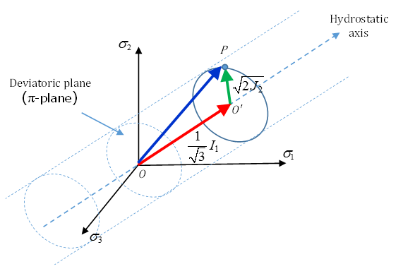
Figure 2. Stress State of P
Here, is the second invariant of deviatoric stress with .
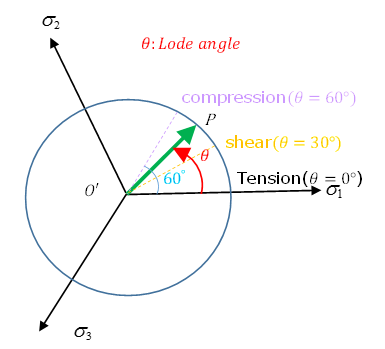
Figure 3. Stress State with Different Lode Angle
| Lode Angle Parameter | Lode Angle | Stress State |
|---|---|---|
| 1 | 0 | Uniaxial tension + hydrostatic pressure (triaxial tension or axisymmetric tension) |
| 0 | 30 | Pure shear + hydrostatic pressure (plane strain) |
| -1 | 60 | Uniaxial compression + hydrostatic pressure (axisymmetric compression) |
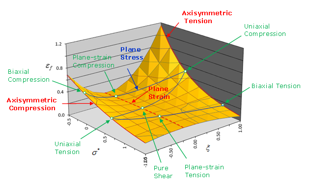
Figure 4. 3D Failure Surface
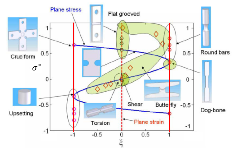
Figure 5. Stress State and Lode Angle for Various Tests
Example /TABLE, dimension=3
/TABLE/1/4711
failure plastic-strain vs triaxiality and strain rate
#dimension
         3
#---1----|----2----|----3----|----4----|----5----|----6----|----7----|----8----|----9----|---10----|
#   FCT_ID                   strain_rate          Lode_angle
      3000                          1E-4                  -1
      3001                           0.1                   0
      3002                           1.0                   1
....
Figure 6. Failure Surface when table_ID1 references a /TABLE with dimension=3
Scaling Failure Strain
- General scaling factor
- Scale factor based on element size
- Scale factor based on temperature
Element Length Dependency
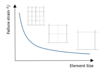
Figure 7. Influence of Element Mesh Size on Material Failure in Numerical Simulation
- Element size function scale factor
- failure strain scale factor as a function of the normalized element size (defined via fct_IDel), and is the reference element size used to normalize the element size
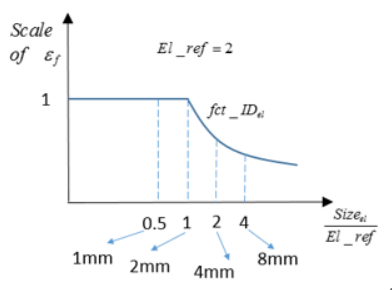
Figure 8. Example of Element Size Scale Factor Function fct_IDel in /FAIL/TAB1
Temperature Dependency
- Temperature function scale factor
- Failure strain scale factor as a function temperature defined via fct_IDT.
Scaling the failure strain based on temperature works with any material that has /HEAT/MAT defined or materials that include thermos plasticity such as /MAT/LAW2 (PLAS_JOHNS).
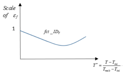
Figure 9. Influence of Temperature on Material Failure with fct_IDT in /FAIL/TAB1
Element Failure Treatment
In /FAIL/TAB1 an accumulative damage model is used. The damage can be output for contour plotting using the Engine options, /ANIM/SHELL/DAMA or /ANIM/BRICK/DAMA.
- The change in plastic strain of the integration point
- Plastic failure strain for the current stress triaxiality
- and
- Damage parameters
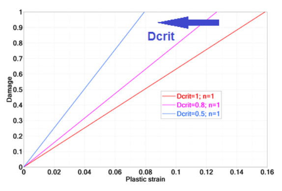
Figure 10. Influence of in /FAIL/TAB1
It is also interesting to understand the influence of the damage accumulation parameter, in Equation 10.
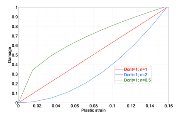
Figure 11. Influence of Damage Parameter
Material Instability (Diffuse Necking)
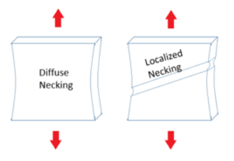
Figure 12. Sketch of Diffuse Necking and Localized
In /FAIL/TAB1 it is possible to account for the material instability (diffuse necking) with options table_ID2, or Inst_start and Fad_exp.
with being the diffuse necking strain based on the current stress triaxiality.
The strain at which instability starts could be either input with a curve (blue curve in Figure 13) using table_ID2 or input as a constrain strain using the option Inst_start.
- If material instability is not included then damage is calculated using the red failure curve in Figure 13
- If material instability is included and modeled using the curve input
(table_ID2) then:
- Damage due to diffuse necking starts when the plastic strain defined by the blue curve in Figure 13 is reached.
- Damage due to diffuse necking is linear if Fad_exp=1 is used. Increasing the Fad_exp leads to more energy dissipated during damage. Figure 13 shows the influence of Fad_exp from 1 to 10 in stress-strain curve. It is recommend to use a Fad_exp value of 5 to 10.
- Once the strain reaches the red curve the element fails.
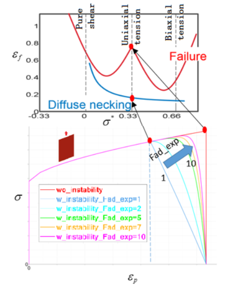
Figure 13. Influence of Parameter Fad_exp and Material Instability Region
- If only Inst_start is used without curve input in
table_ID2, then the diffuse necking
plastic strain is the constant value, Inst_start, for all
stress triaxiality.
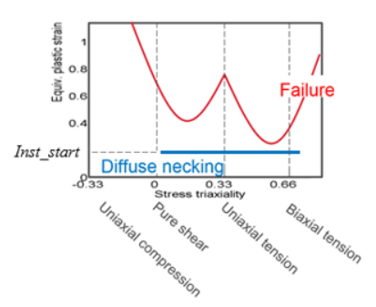
Figure 14. Constant Inst_start Describing Diffuse Necking
Currently diffuse necking (material instability) in /FAIL/TAB1 can only be used with material law numbers > 28.