Friction Correlations
The friction in the Flow Simulator element can be calculated by the given equation, where:
If ReDh < ReTurb, laminar friction calculations take place, otherwise, the turbulent friction calculation routine is used.
| Nomenclature | Subscripts |
|---|---|
| f: friction | F: fanning |
| Re: Reynolds number | D: darcy |
| FMULT: friction multiplier | turb: turbulent flow |
| ε: sand grain roughness | lam: laminar flow |
| A: Cross sectional area | Abuaf: Abuaf friction relation |
| L+: Inlet station + 1/9 of 2nd station | Smooth: smooth surface |
| XMU: dynamic viscosity | Rough: rough surface |
| W: mass flow rate | SJ: Swamee-Jain approximation |
| X: station length | Dh: hydraulic diameter |
| L: equivalent diameter |
Laminar Friction
Calculates the friction coefficient for laminar flow in shaped ducts based on the references Yunus A. Cengel, 2006 and Bruce Munson, 2005.
For a Tube Element, Laminar Friction Inlets effects can be accounted. Friction coefficient for hydrodynamically developing flow with “Muzychka Yovanovich Laminar Inlet Effects” can be calculated as:
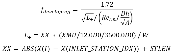
The friction coefficient for combining developing flow and fully developed flow can be calculated as:
Darcy type friction is calculated as
Fanning type friction is calculated as:
Turbulent Friction
Calculates the turbulent friction for smooth or rough walls.
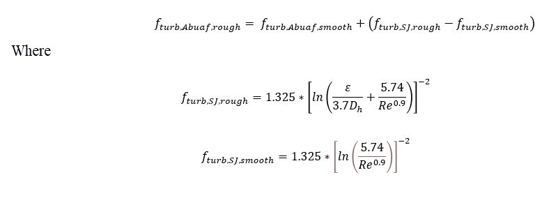
- Abuaf Friction Relation
- The Abuaf friction relation should generally be used for smooth walled tubes.
(8) 
In Flow Simulator, you have the option to use the Abuaf friction relation together with wall roughness. The following adjustment equation is used:
(9) 
- Swamee-Jain Approximation of the Colebrook-White Equation (Moody Diagram)
-
(10) 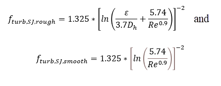 The Darcy and Fanning type frictions are calculated as:
(11) 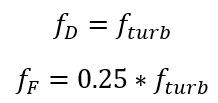
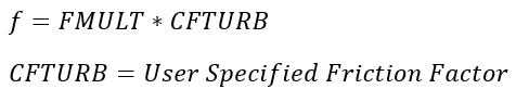
- User-specified Friction Factor
-
(12) 
Roughness
| ε=5.863∗Ra, | Ra=Average Absolute Roughness |
| ε=3.100∗Rrms, | Rrms=Root Mean Square Roughness |
| ε=0.978∗Rzd, | Rzd=Peak to Valley Roughness |
Non-Circular Shapes in Flow Simulator Tubes
The friction factor and heat transfer coefficient (HTC) correlations were developed for circular pipes. The traditional method to use these correlations on non-circular shapes is to calculate a hydraulic diameter based on the shape area and perimeter.
The errors associated with this method can be +/-40% for laminar flow but less for turbulent flow, +/-15% (see White, ref 3).
A more accurate option is to adjust the hydraulic diameter with a friction factor ratio (see White, ref 3). The effective hydraulic diameter can then be used in the friction factor and HTC correlations.
The following table summarizes the relationship between the Dh based on 4*A/P and the effective hydraulic diameter.
| Shape | Effective Dh Equation | Aspect Ratio (AR) |
|---|---|---|
| Circle | AR=1 | |
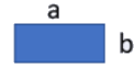
| Rectangle
|
AR=b/a | |
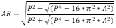
| Ellipse
|
AR based on area and perimeter of the ellipse.
|
|
| Isosceles Triangle
|
AR based on area and perimeter of the triangle.
|
|
| Annulus
|
AR=b/a | |
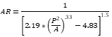
| Freeform (Arbitrary- Shape) |
AR based on area and perimeter of freeform shape using a
rectangle equation.
|


See Blevins (ref 15) and Muzychka et al. (ref 50) for additional information.
If the compressible tube, advanced orifice, and incompressible tube have a cross sectional shape that is not circular, the equations in this table are used for the effective hydraulic diameter equation.