Spatial and temporal definition
Introduction
The force computation is done on a geometrical support and eventually on a time interval defined by user.
For needs of compatibility with the vibro-acoustic or mechanical software, or in order to reduce the working time, geometric reconstruction and temporal duplication tools are available.
3D geometric reconstruction (automatic)
The mechanical software is 3D based. Consequently, whatever the initial Flux geometry may be, all the files exported by Flux represent results in 3D.
The geometric reconstructions run by Flux at the export are the following :
- A 2D project is reconstructed in 3D (with the number of elements in depth specified by user at the export)
- For a computation on Flux mesh, a model with symmetries and periodicities is reconstructed for the complete device (optional)
Temporal duplication: presentation
In the computation box of forces, user can choose the option of a temporal duplication, for time periodic devices, especially motors. This consists in transmitting the computed forces over a defined time interval, in order to automatically obtain the values across a mechanical period.
The advantages are :
- The computation of the forces is faster
- There is no need to solve the project on an entire mechanical period
Temporal duplication: in practice
User has the option to choose a time interval corresponding to one portion 1/n* of the mechanical period.
*n : an integer number, worth minimum 2p (p : number of pairs of poles) for the electrical motors
Temporal duplication: warnings
- Warning 1: the initial and final point of the time interval must merge. For example, if the period is of 0.06 seconds we will take :
- An interval of 0.01 to 0.07 seconds without duplication
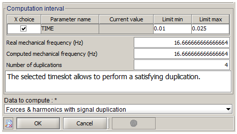
- An interval of 0.01 to 0.025 seconds for a duplication of 4 times
- Warning 2 : one should not take as a first step in the calculation of forces the first step of calculation of the solving scenario for reasons of numerical initializations
Temporal duplication: verification
The accuracy of the results will depend on the chosen time interval. If the fraction 1/n of the period is not defined with an entire n, then the results will be distorted.
In the computation box, once the time interval is introduced and the choice on the time duplication has been carried out, the user has the option to verify the accuracy of his computation (before launching it) by comparing :
- The real mechanical frequency
- The computed mechanical frequency (using the chosen time interval)
The number of duplications, which is always a whole number, is also given. A message indicates the possibility or not for the software to apply the temporal duplication.
Example
The image below represents the part on the time interval of computation in the computation box. In this case, the machine rotates by 1,000 rpm, therefore the mechanical period is of 0.06 seconds. The machine has two pairs of poles, therefore it can choose a time interval at least equal to 1/2p=1/4 of the period (choice made in this case).

Time step (frequency analysis)
In Flux transient application, user chooses in the solving scenario a time interval and a time step. And in the forces computation box, a time interval representing one period is chosen (or a part of it, with signal duplication).
In case of frequency analysis, the time step should be defined from the number of harmonics to analyse.
The number of harmonics is deduced from the number of time steps of the forces computation box as explained in the following program:
N_step: number of time steps in the time interval of the computation boxN_harm: number of harmonicsInitialization: N_harm=2While (N_step-1)/2 >= N_harm:N_harm=N_harm*2So N_harm has the following form: 2^n ; with n an integer
The N_harm obtained represents the number of harmonics for all the spectrum (negative and positive frequencies).
In physical applications, only the positive part of the spectrum is considered.
N_harm=N_harm/2This value is available in the forces computation box when editing it after a computation, as shown in the following screen shot:

The following table illustrates the previous program by giving the computed harmonics number associated to the steps number:
| Steps number | Computed harmonics number |
|---|---|
| 6 to 8 | 2 |
| 9 to 16 | 4 |
| 17 to 32 | 8 |
| 33 to 64 | 16 |
| 65 to 128 | 32 |
| 129 to 256 | 64 |
| 257 to 512 | 128 |
| 513 to 1024 | 256 |
The harmonics frequency step is defined by: f=1/T=1/(dt*(N_step-1));
with dt : the time step and T: the period
The first harmonic has the frequency=0 Hz (corresponding to the DC component).