Evaluate sectional properties from a section cut on both 1D and 2D
elements.
Restriction: Only available in the Nastran
and OptiStruct solvers in the Aerospace user profile. The
tool supports 1D (CBAR, CBEAM, CROD) and 2D elements and multi materials, but is
limited to metallic isotropic materials.
From the menu bar, click Aerospace > Beams > Section Cut.
Use this tool to intersect a selection of elements, 1D and 2D, and evaluate sectional
properties:
Area moments of inertia
Flexural stiffness
Torsional stiffness
Neutral axis position
The tool can create multiple sections at a time and hence generate beam linking each
section.
Table 1. Section Cut Description
Option
Values
Description
Result
Section method
By Plane
Auto
Define how sections are defined.
If Auto, all section options are disabled except Number of
cuts.
Section system
Global
Local
Define which system section's normal is defined.
If local, a system selector is activated.
Section normal
Normal axis
Reverse normal
Global vertical
axis
Define section cut normal axis. Global vertical axis is projected
on plane to define the local vertical axis.
Defines section plane and local axis.
Section location
Offset from origin
Nodes/points
Define section's base:
Picking node/point list
By offset from origin and cuts
Ends section definition.
Elements to include
Element selector
Select elements to include in section cut.
Defaults to displayed elements if no selection.
Calculate inertia
Neutral axis
Centroid
Base point
Position where area moments of inertia are reported.
Centroid is geometric barycenter while neutral axis is calculated
as weighted average center.
Include shells
True/false
Use offset
Consider shell elems from selection. Consider or not offset on
shells.
Shells are supposed to be perpendicular to section. Intersection
is then a rectangle with height equal to thickness.
Include beams
True/false
Use offset
Consider beam elems from selection. Condsider or not beam
offset.
Consider contribution of beam sections to total area and
MoI.
Include rods
True/false
Consider rod elems from selection.
Rod elements contribute only to total area.
Create element set
True/false
Generate a set of elements intersected by the section.
One entity set per section. Can be viewed in Review mode.
Create section cut data
True/false
Detail data
Generate a table with all sectional properties per
section.
One table entity where each row is a section. Columns are
sectional property attributes. This table is used in review
mode.
Create node
True/false
Centroid
Neutral axis
Both
Create a node at the section's center or neutral axis or at both
locations.
Node(s) created at each section.
Create beamsection
True/false
Keep lines
Create a beamsection from shell intersection only. Keep or delete
lines created at plane intersection with shells.
One beamsection per section. Lines in either current or new
components.
Create beam
True/false
Centroid
Neutral axis
Creates a beam element between two successive sections.
1D beams with property assigned.
Expected Results
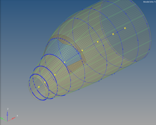
In the example below a fuselage is cut using eight nodes sampled along the x axis.
Beam elements were created at centroid (in a new component) and beamsections where
generated while keeping lines. The result after clicking
Apply is shown in the image below.
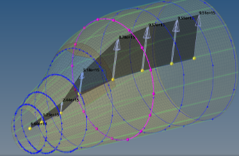
After clicking Review the tool opens a table with sectional
properties. By selecting a cell in column Table ID a graphic object displays the
section intersection with mesh, with a sphere at each intersected 1D element.
Clicking Plot draws selected data name along the element
path. Figure 1. . Section cuts and beam created Figure 2. . Review sectional properties