Setup Modal Analysis
Define modal analysis cards, such as extraction methods, frequency range, modes to expand, iterative solver tolerance, modes significance level and solution control options.

Figure 1.
View new features for Engineering Solutions 2022.2.
Engineering Solutions is a modeling and visualization environment for NVH, Squeak and Rattle Director, Crash, CFD, and Aerospace using best-in-class solver technology.
Discover Engineering Solutions functionality with interactive tutorials.
Noise, Vibration and Harshness (NVH) is an important vehicle attribute that directly affects the customer experience.
Use the Squeak and Rattle Director tool to create evaluation lines, evaluate them and optimize the interfaces to eliminate squeak and rattle issues.
The Crash application offers a tailored environment in HyperWorks that efficiently steers the Crash CAE specialist in CAE model building, starting from CAD geometry and finishing with a runnable solver deck in Radioss, LS-DYNA and PAM-CRASH 2G.
HyperWorks offers high quality tools for CFD applications enabling the engineer to perform modeling, optimization and post-processing tasks efficiently.
Essential utility tools developed using HyperWorks-Tcl.
The Aerospace menu is a useful utility to build and view aerospace models.
Provides tools to create and manage connectors.
Analyze a summary of a part’s statistics using the Part Info tool.
Create pretension loads in 1D and 3D bolts.
Create or open a fatigue analysis setup process.
Check the connectivity between two or more components.
Setup a frequency response analysis with a series of step-by-step process templates.
Manage all of the IDs for the entities that you create, and define ID ranges for all of the entities in each Include file in relation to the full model in order to avoid ID duplication.
Create boundary conditions of any load collector type other than ACTIV using the BCs Manager tool.
Check components or groups for element penetrations and intersections using the Penetration Check tool.
Manage and review all rigid bodies in the model using the RBODY Manager.
Automate the grouping and display of model components through the entity set functionality using the Sets Browser.
Export an input deck, for the appropriate solver, in order to simulate the deformation of the seat under the dummy. The simulation result files can be imported to update the initial FE model and remove the intersections and penetrations between the dummy and the seat.
Create the /TH/SPRING card, which supports time histories with spring output using the Relative Displacement tool.
Review details about Mass, Center of Gravity (Cog) and Inertia of your model.
Display/review and modify frequently used coordinate systems used in CAE analysis.
Setup a DDAM analysis for Abaqus, and use the Shock Spectra curves for a subsequent Response Spectum Analysis.
Define modal analysis cards, such as extraction methods, frequency range, modes to expand, iterative solver tolerance, modes significance level and solution control options.
Use the Transformation Tool to translate, scale, reflect or rotate elements with multiple numbers of copies, including properties and loads, attached to them.
Provides functions to help you morph the shape of a finite element model.
Engineering Solutions Optimization technology is supported by OptiStruct.
Solver interfaces supported in Engineering Solutions.
A solver interface is made up of a template and a FE-input reader.
Support provided by the CAD readers and writers.
Browsers supply a great deal of view-related functionality by listing the parts of a model in a tabular and/or tree-based format, and providing controls inside the table that allow you to alter the display of model parts.
Panels contains pre-processing and post-processing tools.
Create, edit, and cleanup geometry.
Different types of mesh you can create in HyperWorks.
Create connections between parts of your model.
Create, organize and manage parts and subsystems.
Perform automatic checks on CAD models, and identify potential issues with geometry that may slow down the meshing process using the Verification and Comparison tools.
Overview of how to build a finite element model.
Morph the shape of your finite element model.
Setup an Optimization in Engineering Solutions.
Convert finite element models to another solver format.
Study relationships between data vectors in results files.
Learn how to use post-processing functions.
Essential utility tools developed using HyperWorks-Tcl.
Define modal analysis cards, such as extraction methods, frequency range, modes to expand, iterative solver tolerance, modes significance level and solution control options.
Define modal analysis cards, such as extraction methods, frequency range, modes to expand, iterative solver tolerance, modes significance level and solution control options.
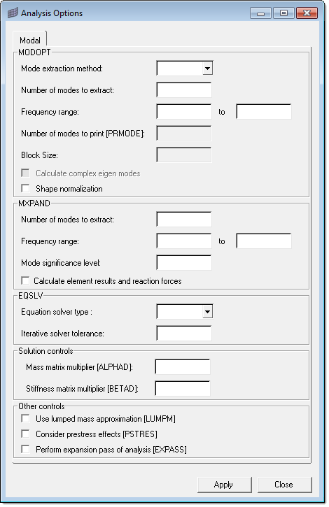
All commonly used cards and options for modal analysis in the ANSYS solver are listed in the dialog. You do not need to search for relevant cards in the control card list, and you do not need to know the control cards that are used for modal analysis. All other implied ANSYS cards, such as /SOLU, SOLVE are set up automatically. If any option or card is not required, then default values will be exported. For example, in the image shown below, if Mass and stiffness matrix multiplier value need not required.
If modal analysis needs to be carried out in the ANSYS solver, this dialog needs to be set up before exporting the model to an ANSYS deck.

© 2022 Altair Engineering, Inc. All Rights Reserved.
Intellectual Property Rights Notice | Technical Support | Cookie Consent