This manual provides a detailed list and usage information regarding command statements, model statements, functions and
the Subroutine Interface available in MotionSolve.
Model ElementSpecifies an analytical bearing that overtakes the radial and axial loads in both directions. This bearing cannot
overtake any tilting moments.
Model ElementCoupler defines an algebraic relationship between the degrees of freedom of two or three joints. This constraint element
may be used to model idealized spur gears, rack and pinion gears, and differentials as simple constraints that relate
the displacements in a set of joints.
Model ElementThe DeformCurve element allows you to represent a curve defined in the model as a DeformableCurve element. The graphic is defined by a number of straight line segments connecting vertices on the curve defined by
DeformableCurve reference.
Model ElementThe DeformSurface element allows you to represent a deformable surface defined in the model as a DeformSurface element. The graphic is defined by a number of straight line segments connecting vertices on the surface defined
by DeformSurface reference.
Model ElementDv defines a special type of solver state variable. It is used in the evaluation and computation of design sensitivity
as a design parameter. Its value is modified during the simulation in case of Design Sensitivity Analysis.
Model ElementEquilibrium defines the solution control parameters for Static and Quasi-static analysis. These parameters control the accuracy
the solution and the method to be used for solution.
Model ElementField defines a force and torque acting between two markers, I and J. The force and torque can only be a function of time
and the relative displacement between the I and J markers. The six components (three forces and three moments) are defined
in the coordinate system of the J marker.
Model ElementFlexBody defines a flexible body object in MotionSolve. This entity has mass and inertia properties, like a rigid body. In addition, it has flexibility properties that
allow it to deform under loads.
Model ElementThe Friction element is used to specify joint friction in a specific joint in your model. Friction is supported only in the following
types of joints: revolute, spherical, translational, cylindrical and universal. MotionSolve uses the LuGre (Lundt-Grenoble) model for friction.
Model ElementThe Frustumelement allows you to represent the portion of a cone that remains after its upper part has been cut off by a plane
parallel to its base, or that is intercepted between two such planes.
Model ElementThe GCON element is used to specify a user defined general constraint. Your constraint equations may involve position as well
as velocity measures of the system. Although MotionSolve provides a large set of constraints to choose from (see JOINT), there are situations that require non-standard constraints.
Model ElementGse is an abstract modeling element that defines a generic dynamic system. The dynamic system is characterized by a vector
of inputs u, a vector of dynamic states x, and a vector of outputs y. The state vector x is defined through a set of differential equations.
Model ElementJprim is used to remove degrees of freedom between two bodies by specifying
conditions in which the relative translational or rotational motion can occur. Jprim differs from JOINT in that the former specifies mathematical constraints, which may not have
concrete physical realizations like the latter.
Model ElementThe LineMesh element connects a number of vertices in space with straight lines. It is similar to the Outline element except it does not require markers. You can pass coordinates to the LineMesh geometry.
Model ElementMarker defines an orthonormal, right-handed coordinate system and reference frame in MotionSolve. A Marker must belong to a part. The body can be any type: rigid, flexible, or point.
Model ElementMate is used to specify general mating constraints between geometric
primitives. Mate differs from JOINT and JPRIM in that it specifies more general constraints based on distance, tangency,
and coincidence relations between mating
geometries.
Model ElementNforce defines a force and torque acting between many markers. The force and the torque can only be linear functions of
the relative displacement and velocity of the various markers.
Model ElementThe ParamCurve element allows you to represent a curve defined in the model as a Curve element. The graphic is defined by a number of straight line segments connecting vertices on the curve defined by
Curve reference.
Model ElementPtcv defines a higher pair constraint. A fixed point on one body slides on a curve that is fixed on a second body. The
point is not allowed to lift off the curve.
Model ElementPTSF defines a higher pair constraint. A fixed point on one body slides on a surface that is fixed on a second body. The
point is not allowed to lift off the surface.
Model ElementRv defines a special type of solver state variable. It is used in the evaluation and computation of design sensitivity
as a response variable.
Model ElementSfsf defines a higher pair constraint. The constraint consists of a surface on one body rolling and sliding on a surface
on a second body. The surfaces are required to have a unique contact point.
Model ElementThe UserMsg element allows you to control the output of MotionSolve messages. Any message that MotionSolve prints to standard output goes through the
This manual provides a detailed list and usage information regarding command statements, model statements, functions and
the Subroutine Interface available in MotionSolve.
The MotionSolve bearing API statements help you model
analytical bearing elements.
Bearings are involved in almost all mechanisms, such as gearboxes, engines, robotic
arms, and so on. In traditional multibody dynamics, bearings are often simplified by
kinematic constraints, such as revolute joints or bushings. Kinematic constraints
can lead to constraint redundancy that often results in some constraint being
removed. While the kinematics of the mechanism are preserved, the load distribution
between the bearings is wrongly represented. Similar issues can occur if bearings
are represented by linear bushings, since the compliance of bearings is non-linear.
Alternatively, bearings can be represented by a multibody subsystem, where raceways
and rolling elements are represented by rigid or flexible bodies in contact with
each other. However, those subsystems are computationally inefficient, especially if
there are too many bearings within a mechanism. To overcome this impediment,
MotionSolve contains bearing components designed
particularly for system analysis. In other words, they were designed to accurately
replicate the non-linear compliance of bearings but are simplified enough to
accommodate the need for high-computational performance. The bearing components
require only simple user inputs that can be found in many bearing catalogues. Use
the results to study bearing loads and their life expectancy. The bearing components
are developed on top of the MotionSolve API. The
bearings' library currently supports the following bearing types:
Angular contact ball bearing
Cylindrical roller bearing
Deep groove ball bearing
Spherical roller bearing
Tapered roller bearing
Each bearing consists of an inner and outer raceway that are defined as rigid bodies.
Both raceways are connected to each other by a non-linear spring-damper system that
represents the balls/rollers between the raceways. The spring-damper system is
defined analytically using the Hertzian approach for point contact (balls) and the
Palmgren formula for line contact (rollers). Its stiffness and damping properties
are dependent on the relative position and velocity between the raceways. In the
initial resting position, the local z-axis of the inner/outer race points along the
shaft and the origin of the local frame is at the center of mass.
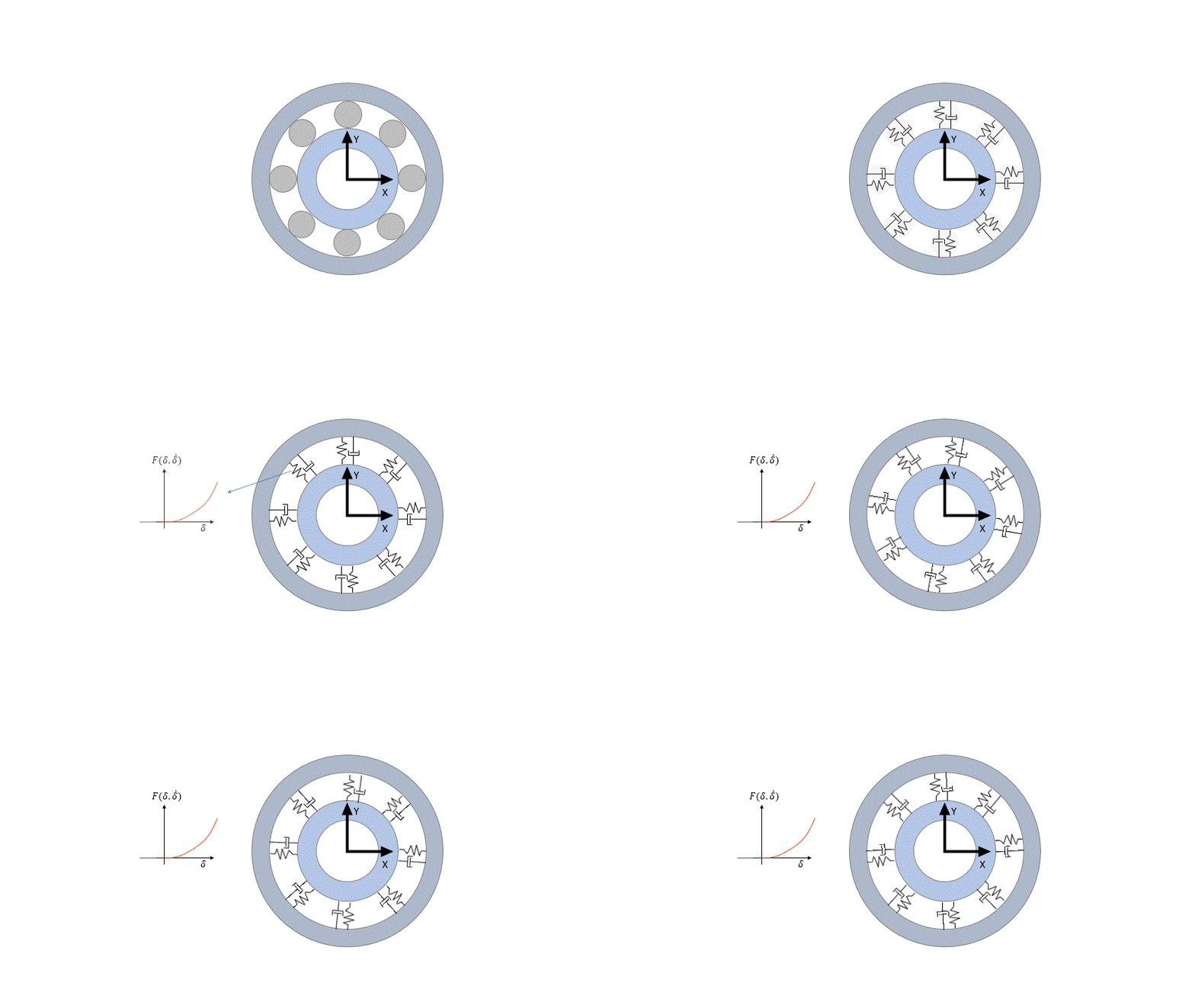
The bearing’s cage and rolling elements are included as one rigid body. Its mass and
inertia is approximated using the rolling element geometries. This rigid body helps
estimate the overall weight of the bearing as well visualize the rotation of the
rollers.
Most of the machinery bearing’s input arguments can be extracted from catalogues and
tables provided by bearing OEMs. Not all internal geometry parameters are provided
in these tables directly, but instead need to be extracted from CAD geometry files
that are provided by the OEMs.
Note: CAD files may not precisely capture the true geometry of
a bearing. However, in most cases, the CAD files are a sufficient starting point
for the bearing model.
The online OEM’s calculators can be used to extract many of the needed parameters,
such as the type and the viscosity of bearing lubricants, or any calculation factor
used for the friction torque calculation.
AngularContactBallBearing Model ElementSpecifies an analytical bearing that overtakes radial and axial loads in one direction.
CylindricalRollerBearing Model ElementSpecifies an analytical bearing that overtakes the primary radial load.
DeepGrooveBallBearing Model ElementSpecifies an analytical bearing that overtakes the radial and axial loads in both directions.
SphericalRollerBearing Model ElementSpecifies an analytical bearing that overtakes the radial and axial loads in both directions. This bearing cannot overtake any tilting moments.
TaperedRollerBearing Model ElementSpecifies an analytical bearing that overtakes the radial and axial loads in one direction.