Analyze a model with contacts to understand the difference between sliding and
separating.
In this lesson you will learn how to:
Create a nut and bolt
Ground the bolt
Run an analysis
View contacts
Redefine the contact type
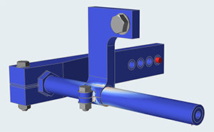
Open the Sway Bar Model
Press F7 to open the Demo Browser.
Double-click the Analysis_Contacts.stmod file to load it
in the modeling window.
Make sure the display units in the Unit System Selector are set to
MPA (mm t N s).
This will be important for comparing analysis results.
Notice that the model already has a load case defined. Our objective for this
load case is to accurately simulate the transfer of loads from the torque
applied at the inside end of the bar to the bracket designated as the design
space.
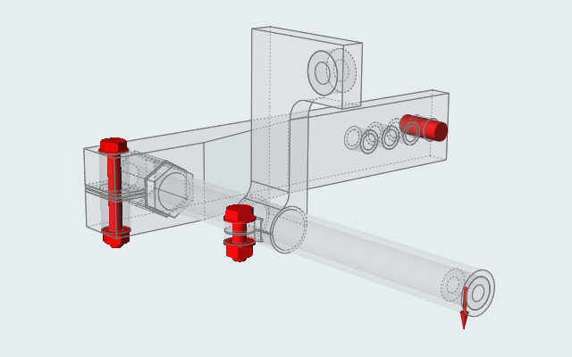
Create Nuts and Bolts in Aligned Holes
Click the Structure tab on the ribbon and select the
Fasteners tool.
The tool finds two locations with aligned holes.
Click Fasten All on the guide bar.
Observe as Inspire creates nuts and bolts in both
locations.
Create a Nut and Bolt in a Single Hole
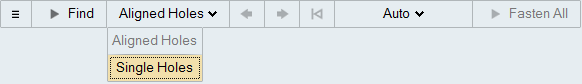
While the Fasteners tool is still active, click Aligned
Holes on the guide bar and select Single
Holes.
Inspire finds multiple locations with single holes.
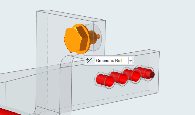
Click to apply a Grounded Bolt in the single hole
location shown below.
Right-click to exit the Fasteners tool.
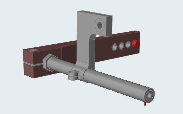
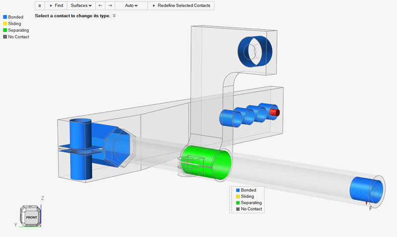
Redefine the Contact
Redefine the contacts in the model before you run an analysis to permit or restrict
their movement.
Select the Contacts tool on the Structure ribbon.
All of the contacts in this model are currently defined as bonded
contacts(default) and are shown in blue.
Left-click the contact where the bar touches the L bracket.
A microdialog appears.
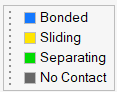
Select the colored buttons on the microdialog to change the contact type.
Select Bonded if parts are bonded or glued
together.
Select Sliding if there is relative sliding
between the parts.
Select Separating if the relative parts can
separate.
Select No Contact if parts are close but you
don't want them to have contact.
Right-click and mouse through the check mark to exit, or double-right-click.
Run the Analysis with Sliding
Redefine the model Contacts to
Sliding.
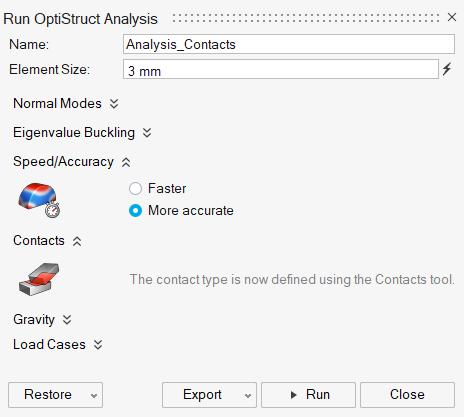
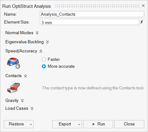
Click Run Analysis on the Analyze icon to open the Run Analysis
window.
Run the analysis using the settings shown below. Change the Element Size to
3 mm, set the Speed/Accuracy to More
Accurate.
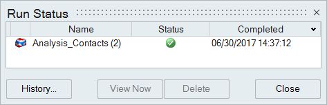
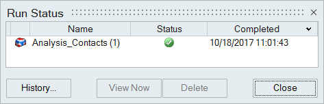
When the run is complete, select the run in the Run Status window and click
View Now to view the results.
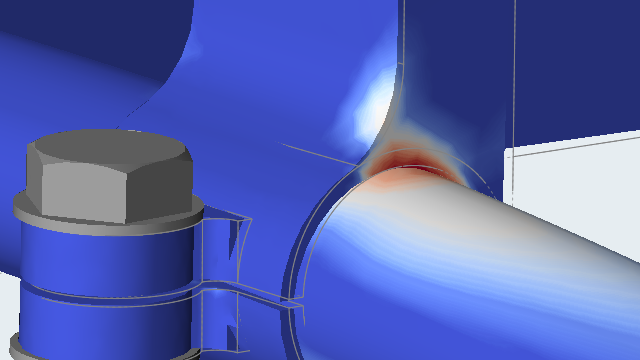
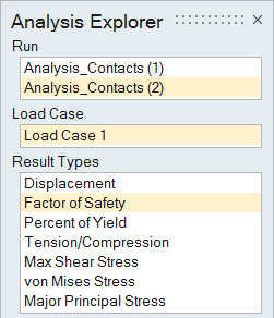
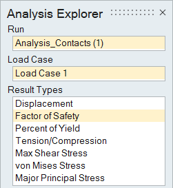
In the Analysis Explorer, select Factor of Safety for
the Result Type.
Click the Show/Hide Deformed State icon on the Analysis Explorer.
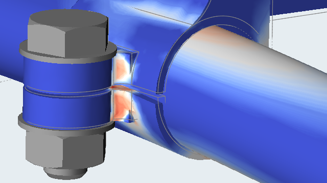
Notice that the L-bracket and the sway bar are acting as if they are attached,
which is incorrect. There should not be local stress in the sway bar where it
meets the L-bracket.
Right-click and mouse through the check mark to exit, or double-right-click.
Note: With Sliding contact types,
you can run the model faster, but the results will not be as accurate.
Rerun the Analysis with Separating
Redefine the model Contacts to
Separating.
Run the analysis again using the settings shown below.
Click Run Analysis on the Analyze icon to open the Run Analysis
window.
When the run is complete, select the run in the Run Status window and click
View Now to view the results.
In the Analysis Explorer, select Factor of Safety for
the Result Type.
Notice that now the sway bar separates from the top of the L-bracket, as it
would in real life.
Right-click and mouse through the check mark to exit, or double-right-click.
Note: With Separating contact types, the model will run slower,
but will better represent the actual physics.


 All of the contacts in this model are currently defined as bonded contacts(default) and are shown in blue.
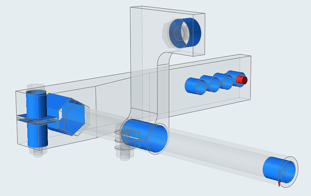
 on the Analyze icon to open the Run Analysis
window.
on the Analyze icon to open the Run Analysis
window.

 icon on the Analysis Explorer.