Beams From Lines
These tools enable the creation of 1D elements from surface lines, organizing them into components. They also offset/orient these elements based on the attached shell elements and calculating properties of these 1D elements from 3D solid or shell FE element sections.
Beams From Lines: Create
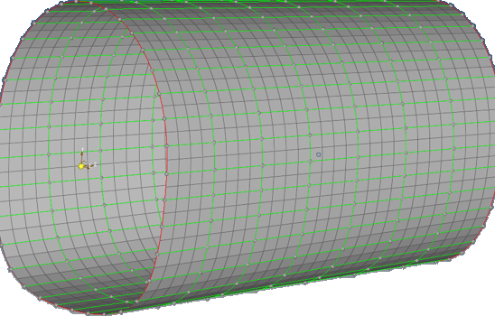
Figure 1. A Shell Element Model with Panel Surface Edges (Green Edges) Where the Beam Will be Created
- Select all of the surface edges. This tool works on surface edges without free floating lines. Therefore, you need to mask or delete all of the free lines.
- From the menu bar, click to import the standard beam section from a
.csv file. In this example the CSV format and the
+Y axis of the beam will be aligned with the shell normal.
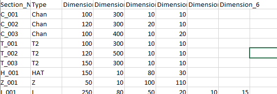
Figure 2. Standard Beam Section Definitions from a .csv File - Select Local as the System Type.
- Assign beam section to each system axis. If the axis does not need a beam, you can make the selection Unspecified.
- Click Create. A beam will be created with the correct
beam section properties and type (CROD, CBAR, CBEAM) along each system
axis.
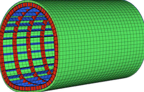
Figure 3. 1D Elements are Created to Match the Shell Elements and Correct Beam Sections are Assigned
Beams From Lines: Organize
- Create empty components in each system direction.
- Move the beams automatically to those components.
Beams From Lines: Update
Use this tool to update 1D element properties, change the orientation, or assign offset to existing BEAM elements. The offset and orientation is based on the attached shell element normal and shell element thickness.
Using the Beam Update tool, beam sections can be automatically calculated from 3D solid or FE shell/beam models.
Figure 4.
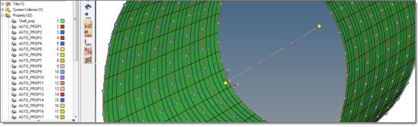
Figure 5.
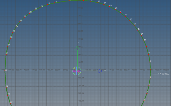
Figure 6. Beam Properties are Calculated and Assigned to Each Beam
You can create a section from composites and generate a VABS file OptiStruct PBEAML using the VABS file. For more information, see OS-T: 9000 OptiStruct and VABS Integration.
Beams From Lines: Display
- Click Pick.
- In the graphics area select a beam.
- Click Display to see the beam's property values.
- Click Clear and repeat the process for the next
beam.
Figure 7.