Elem Offset Panel
Use the Elem Offset panel to create and modify elements by offsetting from a mesh of plate or shell elements.
Location: 2D and 3D pages
The element normals provide directional information.
Solid Layers Subpanel
Before you offset plate elements, make sure that the normals of the plate elements are properly aligned.
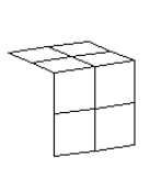 Figure 1. Elements Selected |
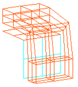 Figure 2. Elements Created, Initial Offset=40 |
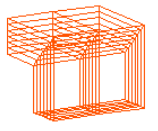 Figure 3. Elements Created, No Biasing Factor |
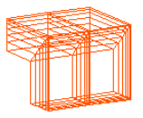 Figure 4. Element Created, Negative Biasing Factor |
*function("HM_COMP_TKvariable1)
 *components(""")
   *format()
       *variableset(variable1,$TK)
 *output()
*return()| Option | Action |
|---|---|
| 3d faces by nodes | Select nodes of 3d elements to offset. |
| Delete 2d elements after | Delete 2d elements after offset. |
| elems to offset selector | Select the elements to offset. |
| along geoms to follow | Select the surfaces or elements to act as guides for the sides of the offset elements. |
| number of layers | Specify the number of layers of elements to build along the normal direction. |
| Use distr thick | Apply the distributed BL thickness
ratio that you defined in the Distributed BL Thickness Ratio dialog. To access
this dialog, click Set distr thick. Clear this checkbox to ignore the defined distributed BL thickness ratio. |
| initial offset | Specify the initial offset from the surface of the plate elements along the positive normal direction. |
| total thickness | Specify the total thickness of the layers of solid elements you want to create. |
| biasing style | Select the biasing style. |
| bias intensity | Specify the biasing intensity value. |
| elements to current comp / original comp | Choose whether to organize the newly created components in the current component, or in the components of the shell elements. |
| corners style |
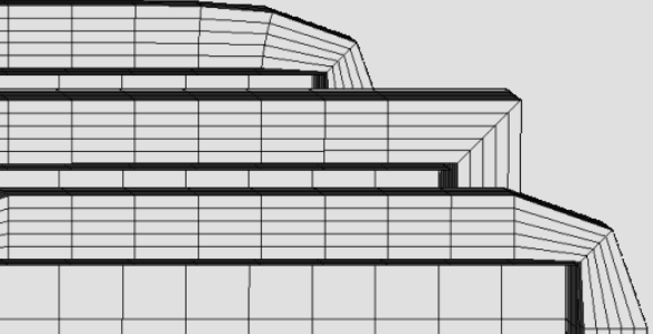 Figure 5. Corner Style Examples. The bottom/front mesh uses rounded corners; the middle mesh uses square corners; the top mesh uses CFD corners (notice that CFD elements "lean" toward the corners). |
Shell Layers Subpanel
Before you offset plate elements, make sure that the normals of the plate elements are properly aligned.
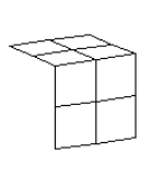 Figure 6. Elements Selected |
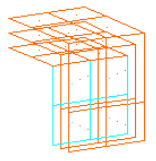 Figure 7. Elements Created with Square Corners |
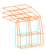 Figure 8. Elements Created with Rounded Corners |
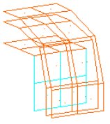 Figure 9. Element Created, Initial Offset=40 |
| Option | Action |
|---|---|
| elems to offset selector | Select the elements to offset. |
| along geoms to follow | Select the surfaces or elements to act as guides for the sides of the offset elements. |
| number of layers | Specify the number of layers of elements to build along the normal direction. |
| initial offset | Specify the initial offset from the surface of the plate elements along the positive normal direction. |
| total thickness | Specify the total thickness of the layers of solid elements you want to create. |
| biasing style | Select the biasing style. |
| elements to current comp / original comp | Choose whether to organize the newly created components in the current component, or in the components of the shell elements. |
| corners style |
Figure 10. Corner Style Examples. The bottom/front mesh uses rounded corners; the middle mesh uses square corners; the top mesh uses CFD corners (notice that CFD elements "lean" toward the corners). |
Shell Offset Subpanel
If you build a mesh on the surface of a CAD solid body, the elements will be aligned out of the object. When you use this tool to offset them to the midsurface of the solid, you will want them to go in the reverse of the element normals.
| Option | Action |
|---|---|
| elems to offset selector | Select the elements to offset. |
| along geoms to follow | Select the surfaces or elements to act as guides for the sides of the offset elements. |
| distance / distance = 1/2 element T |
|
| corners style |
Figure 11. Corner Style Examples. The bottom/front mesh uses rounded corners; the middle mesh uses square corners; the top mesh uses CFD corners (notice that CFD elements "lean" toward the corners). |
Thicken Shells Subpanel
| Option | Action |
|---|---|
| elems to offset selector | Select the elements to offset. |
| along geoms to follow | Select the surfaces or elements to act as guides for the sides of the offset elements. |
| shells are on the midsurface / shells are on an outer surface |
|
| thickness = | Specify a thickness value. |
| elements to current comp / original comp | Choose whether to organize the newly created components in the current component, or in the components of the shell elements. |
| corners style |
Figure 12. Corner Style Examples. The bottom/front mesh uses rounded corners; the middle mesh uses square corners; the top mesh uses CFD corners (notice that CFD elements "lean" toward the corners). |
Command Buttons
| Button | Action |
|---|---|
| offset+ | Extrude/offset shells in the positive normal direction. |
| offset- | Extrude/offset shells in the negative normal direction. |
| thicken | Perform the thickening when shells are
on the midsurface. Note: Available in the Thicken Shells subpane.
|
| mesh | Create the thin solid mesh in
accordance with the criteria specified in the inputs. Note: Available in the Thin
Solids subpanel.
|
| reject | Undo any changes made to elements, or thin solid element creations. You cannot reject changes after exiting the panel, but you can still reject after switching to a different subpanel and returning. |
| return | Exit the panel. |