Check Connector Quality
Use the Quality controller to perform various checks on connectors and realized FE.
The Quality controller is used to determine if the model contains duplicate connectors or if the realized elements meet the quality requirements such as the length of 1D elements and their perpendicularity to the shells they connect.
-
Select a check type and define any options.
Check Type Description Check and Fix Action Duplicates Finds all duplicate connectors (two or more connectors that are located within the set tolerance and connect the same link entities (Parts) are considered duplicates) Removes duplicate connectors (according to the ID Manager selected option). Combine Finds all adjacent connectors (two or more connectors that are located within the set tolerance and connect different parts are considered adjacent). Combines all adjacent connectors into one connector that connects all the link entities. Find too long Finds all connectors whose length exceeds the length specified by the set tolerance. - Find too short Finds all connectors whose length falls short of the specified length by the set tolerance. - Find too long or short Finds all connectors whose length deviates more than the specified length by the set tolerance. - Find too close to edge Finds spot connectors whose distance to a feature or free edge is smaller than the set tolerance. Moves connectors found along the surface they are on, by the required distance to satisfy the specified tolerance. Collinearity Checks if the angle between the link entities of a connector is within the set tolerance. If the diameter option is filled, a check is performed (only if the first check is satisfied) to ensure that the parallel area is big enough for a realization with the specified diameter. - 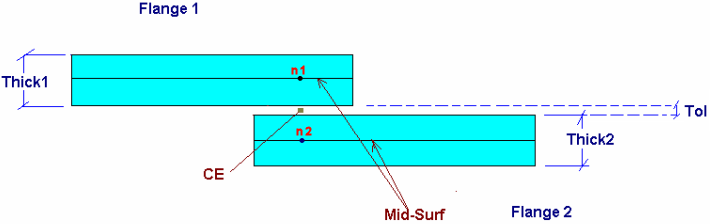
Figure 1. Correct Projection Length is the Distance Between n1 and n2Check Type Options Duplicate Combine
- Tolerance
- Specifies the distance between connectors in order to be considered duplicate/adjacent.
- Consider Unrealized Only
- Specifies whether realized connectors will be included in the check or not.
- ID manager
- Specifies the retain/remove behavior.
Find too long Find too short
Find too long or short
- Tolerance
- Specifies the deviation from the "correct" length
- Length Type
- Specifies if the "correct" length will be user - defined or the average thickness of the parts connected ((T1 + T2)/2) will be used.
- Length
- Only when Length option is selected in the Length Type field.
Find too close to edge - Feature Type
- Lets you select between Free edge, Feature edge, or both.
- Feature Angle
- Maximum angle at which elements are allowed to be connected to each other to be considered a feature.
- Distance
- Specifies the maximum distance from the selected type of edge.
Collinearity - Max. Feature Angle
- Specifies the maximum angle between the connected parts to be considered parallel.
- Diameter
- Specifies the diameter of the desired realization.
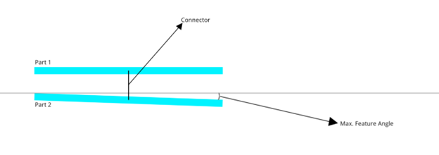
Figure 2. Maximum Feature Angle for collinearity check