Use the automotive section library for rapid concept development in the early phases
of the vehicle design process.
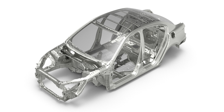
The automotive focused section library promotes rapid creation of full vehicle
architecture concept models. The library consists of various sections from the 2011
Honda Accord Body in White (BiW) model. *
Note: You should be familiar with the
Part Browser before using the section
library.
Figure 1. Sample Body in White model (2011 Honda Accord) Figure 2. Sections from Section Library
From the Assembly ribbon, click the satellite icon
that appears when you hover over the Parts
tool.
The Part Browser opens.
Right-click in the browser and select Library > Libraries.
The Libraries dialog opens.
Click to add a library.
Set the library template to Sections.
Click Add then Connect
When Add is clicked, it automatically extracts the
Sections.zip file found at
<Altair>\hwdesktop\demos\hm\examples\libraryTemplates\part_library\
to the user-defined path.
To access the contents of the library, load
Honda_Accord_Section_Library.hm from the newly created
library path defined in step 5.
The .hm contains the file
hierarchy library structure.
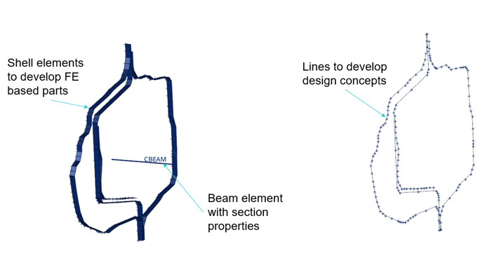
Sample Section
Each section in the section library contains:
A Beam element with a section property
2D elements showing the shape of the section. The 2D element section is
welded at the flanges.
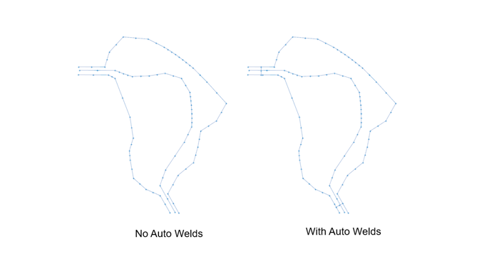
Geometric lines representing the shape of the section that can be used for
concept modeling. The geometric sections are not auto-welded at the
flanges.
Figure 3. Sample Section
Although the geometric section lines are not welded, beam sections are
auto-welded. Figure 4. Beam Section with Auto Welds
Numbering Scheme
The section library follows a numbering scheme that is explained in detail below.
Note: The numbering scheme is not mandatory and you can implement any numbering scheme
of your choice.
Each section can be identified by a 7-digit number
The first digit from the left corresponds to the section’s location. It can
take values of 1, 2, or 3.
1: If the section is on the left side of the vehicle (for example,
left-side B pillar)
2: If the section is on the right side of the vehicle (for example,
right-side B pillar)
3: If the section is in the middle of the vehicle (for example,
tunnel)
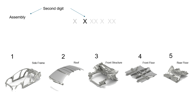
The second digit from the left corresponds to the assembly of the section.
It can take values from 1 to 5.
1: If the section belongs to the Side Frame assembly
2: If the section belongs to the Roof assembly
3: If the section belongs to the Front Structure assembly
4: If the section belongs to the Front Floor assembly
5: If the section belongs to the Rear Floor assembly
Figure 5. Second Digit Representing Different Assemblies
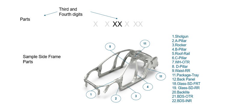
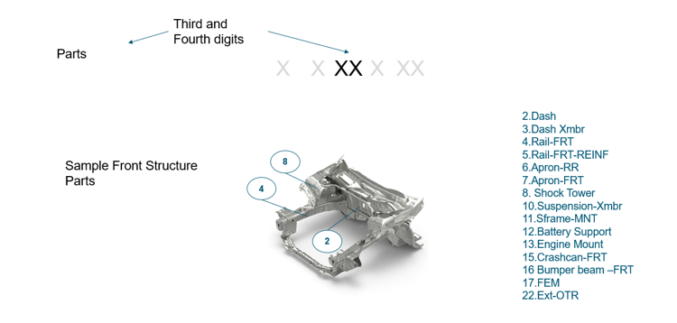
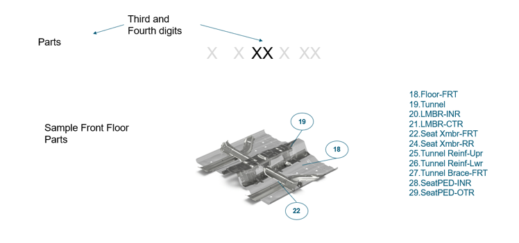
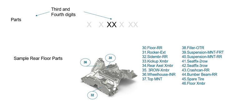
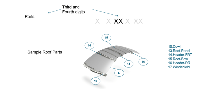
The third and fourth digits correspond to parts from the assembly. Each
assembly has a number of parts; for example, the list of sample parts goes
to 11 in Figure 7.
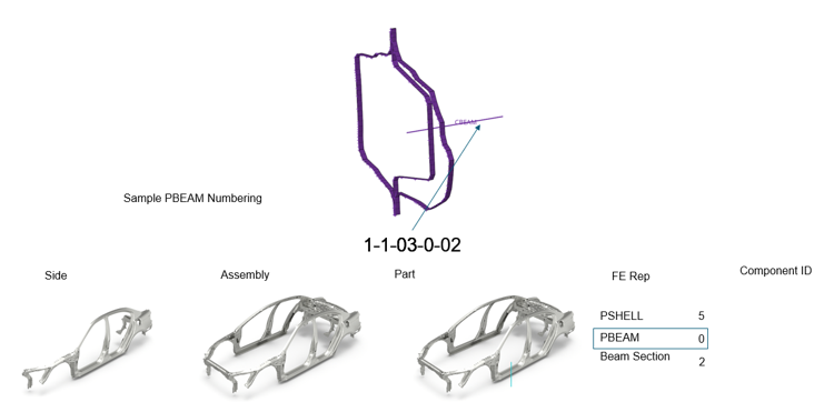
The fifth digit corresponds to the FE representation of the section. It can
take values of 0, 2, or 5.
0: If the FE representation is PBEAM
2: If the FE representation is Beam Section
5: If the FE representation is PSHELL
The sixth and seventh digits correspond to the component number.
An example of the numbering scheme implemented on the left-hand side rocker/sill
section can be seen in Figure 6

 that appears when you hover over the Parts
tool.
The Part Browser opens.
that appears when you hover over the Parts
tool.
The Part Browser opens. to add a library.