Deformable Road
MotionView provides the ability to include soft-soil road deformation in simulations using the soft-soil tire model. The deformable road graphic is created in MotionView using the Road Tools and sent to MotionSolve to simulate the tire-soft-soil dynamics. The soft-soil road deformation can be visualized in HyperView.
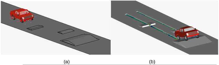
Figure 1. a) Soft-soil road graphics in MotionView; b) Soft-soil road graphics deformed in HyperView
The Road Tool supports the creation of flat and Curved Regular Grid (.crg) roads using the road property file (.rdf). It is also possible to include the different obstacle types available in the soft-soil tire model that deforms along with the road depending on the obstacle material. Refer to Obstacles for more information.
Road Property File
The road property file must contain the required parameters to define a soft-soil road. The element size of the deformable road is defined by the ROAD_INCR in the GRAPHICS block.
Below an example of a flat soft-soil road.
$-----------------------------------------------------------MDI_HEADER
[MDI_HEADER]
FILE_TYPE           =  'rdf'
FILE_VERSION        =  5.00
FILE_FORMAT         =  'ASCII'
$--------------------------------------------------------------------------UNITS
[UNITS]
 LENGTH             = 'm'
 FORCE              = 'newton'
 ANGLE              = 'radians'
 MASS               = 'kg'
 TIME               = 'sec'
$--------------------------------------------------------------------------MODEL
[MODEL]
 PROPERTY_FILE_FORMAT     = 'USER'
 FUNCTION_NAME            = 'mbdtire::ROADSUB'
 METHOD                   = '3D'
 ROAD_TYPE                = 'softsoil'
$---------------------------------------------------------------------PARAMETERS
[PARAMETERS]
 MU                 =  1.0                 $ Friction coefficient
 OFFSET             =  0.0                 $ Offset of soil surface in z direction
 LENGTH             =  300.0               $ Range of soil region in x direction
 WIDTH              =  6.0                 $ Range of soil region in y direction
 NODES              =  1                   $ Number of integration points
 MULTIPASS          =  'TRUE'
$----------------------------------------------------------------SOIL_PROPERTIES
[PROPERTIES]
 PHI                       = 0.49           	$ Angle of internal shearing resistance [angle]
 C                         = 1040.0         	$ Soil apparent cohesion [force/length**2]
 KX0                       = 0.043          	$ Shear deformation module [length/angle]
 KX1                       = 0.02           	$ Shear deformation module [length]
 KY0                       = 0.020          	$ Shear deformation module [length/angle]
 KY1                       = 0.013          	$ Shear deformation module [length]
 KC                        = 950.0          	$ Pressure-sinkage parameter [force/length**(n+1)]
 KPHI                      = 1.528E6        	$ Pressure-sinkage parameter [force/length**(n+2)]
 SINKAGE_EXPONENT          = 1.1            	$ Sinkage exponent n [-]
 C1                        = 0.3            	$ Parameter for wheel angle of maximum normal stress [-]
 C2                        = 0.32           	$ Parameter for wheel angle of maximum normal stress [-]
 SOIL_STIFFNESS            = 1.528E7        	$ Soil elastic stiffness [force/length**3]
 SOIL_DAMPING              = 500.0          	$ Soil damping [force*time/length]
 SOIL_DENSITY              = 1650.0         	$ Soil density [mass/length**3]
$----------------------------------------------------------------------GRAPHICS
[GRAPHICS]
ROAD_INCR   	= 0.050
In order to represent generic road profile defined by a .crg property file, the attribute CRG_FILE needs to be set in the PARAMETERS block of the road.
$---------------------------------------------------------------------PARAMETERS
[PARAMETERS]
 MU              =  1.0                 $ Friction coefficient
 LENGTH          =  300.0               $ Range of soil region in x direction
 WIDTH           =  6.0                 $ Range of soil region in y direction
 NODES           =  1                   $ Number of integration points
 MULTIPASS       =  'TRUE'
CRG_FILE = '<road_path>.crg'Road Positioning
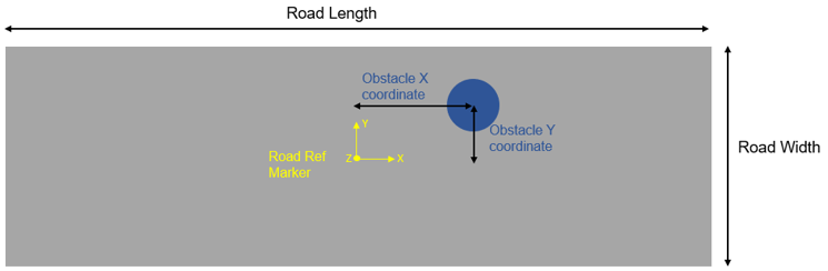
Figure 2. Flat surfaces and an obstacle positioned with the road reference marker
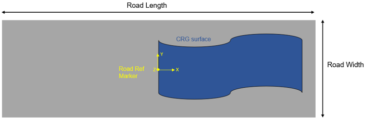
Figure 3. CRG surfaces positioned with the road reference marker on the deformable road
Add a Soft-Soil Deformable Road and Visualize the Results
- Load the soft-soil road property file (.rdf) in the Road Tools
(see the Visualization - Road Tools topic for additional
information). When loading the road property file, an .h3d file and .mdl file are created at the selected path. The road graphics are displayed in MotionView's modeling windows and a graphic system containing the road graphics is defined in the model browser.
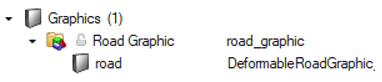
Figure 4. - Add the soft-soil tire and road property files in the Tires entity.
- Run the analysis in MotionSolve.
MotionSolve reads the road .h3d created by the Road Tools and generates an additional SSR (soft-soil road) file which has the name <MotionSolve_result_xml_name>_softsoil_road.ssr during run time and an additional H3D file with the name <MotionSolve_result_h3d_name>_softsoil_road.h3d while writing the results. The softsoil_road.ssr contains the information about the road graphic nodes deformed during the simulation which is used to create the deformed softsoil_road.h3d file.
- Post-process the analysis in HyperView.
Once the simulation in completed, open the model animation results in HyperView. This result does not contain the deformable road, to visualize the road deformations, load the softsoil_road.h3d file using HyperView's Load Model and Results Overlay option.