What's New
View new features for MotionSolve 2022.3.
Altair Multi Body Solutions 2022.3 Release Notes
Highlights
- Entity Editor.
- Entity Browser.
- Run with live animation updates.
- Vehicle Dynamics solutions as an extension with a dedicated page, workflow, and tools.
- New library of components replacing the Auto Entities.
- Deformable roads for soft-soil terrains.
- Siemens MF-Tyre/MF-Swift version up to 2212.
- Cosin Ftire version up to 2022-4.
- AcuSolve co-simulation update.
- Support for Jupyter Notebook.
- Deprecation of the Abaqus solver mode.
New Features
- Entity Editors and Panel Removal
- For the previous release, Entity Editors were introduced in the
HyperWorks MotionView interface. In this release, the editor has been
expanded to include the following entities:
- Control State Equations
- Field
- NLFE Body
- Entity Browser
- In this release, MotionView introduces the Entity
Browser user interface element. This is a dockable
browser that you can access from the View menu. The Entity Browser
contains MotionView entities. In a future release, MotionView will
support user-defined customized entities which will be stored, listed,
and accessible from the Entity Browser. Use the Entity Browser to:
- Search for an entity.
- Double-click on an entity to add it to the model.
- Add customized entities using an extension and the Extension Manager.
- Vehicle Solutions Extension with Dedicated Page, Workflow, and Tools
- Vehicle solutions in MotionView is a collection of tools and model libraries that enables the creation of motorcycle, car, truck, and bus models. It consists of dedicated libraries of suspension models that can be used to assemble full vehicle models, as well as a component library that simplifies using vehicle components, such as tires, shock absorbers, bushings, air springs, and other specific tools, to provide an easy and automatic way to create leaf springs, track models, road graphics, and vehicle events.
-
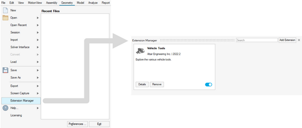
Figure 1. Vehicle Tools Extension -
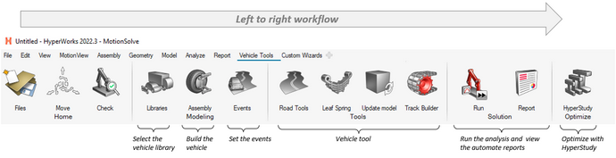
Figure 2. Vehicle Tools Page in MotionView -
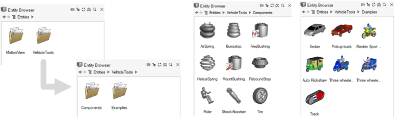
Figure 3. Vehicle Tools Folder in the Entity Browser - New Component Library for Auto Entities
- MotionView has a new component library to provide a better user experience in the HyperWorks interface. These components follow the guide bar workflow to connect the collectors and the Entity Editor to edit/modify the parameters.
-
Figure 4. - Deformable Roads for Soft-soil Terrains
- In MotionView, you can include soft-soil road deformation in simulations using the soft-soil tire model. The deformable road graphic is created in MotionView using the Road Tools and sent to MotionSolve to simulate the tire-soft-soil dynamics. Use HyperView to visualize and post-process the soft-soil road deformation, including the Plastic Sinkage contour.
-
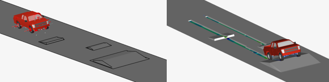
Figure 5. Deformable Road in MotionView (left) and HyperView (right) - AcuSolve Co-simulation Support
- MotionSolve can co-simulate with AcuSolve, Altair’s CFD solver, to incorporate fluid interaction with moving parts in a multi-body simulation. This is enabled in MotionView by using a system from the HyperWorks installation that adds the necessary MotionSolve statements to the model. In this release, native GUI support for fluid interaction with AcuSolve is available. The rigid body entity includes an option to enable interaction with AcuSolve. The remaining necessary solver statements are added automatically to the solver deck upon export. The run with live animation also supports co-simulation with AcuSolve.
- Run MotionSolve through Jupyter Notebook
- MotionSolve has a Python interface called msolve. This means that MotionSolve is available in Python as a library. You can access its functionality through a well-defined set of Python classes, methods, and tools (see the MSolve API Statements in the MotionSolve Reference Guide). In Python, you can access MotionSolve functionality in much the same way you access other libraries, such as numpy or scipy. With this release, msolve is embedded into a Jupyter Notebook. Start Jupyter through the MotionSolve_Jupyter Start menu (Windows) or through the <install_dir>/hwsolvers/script/motionsolve_jupyter.bat/sh script.
-
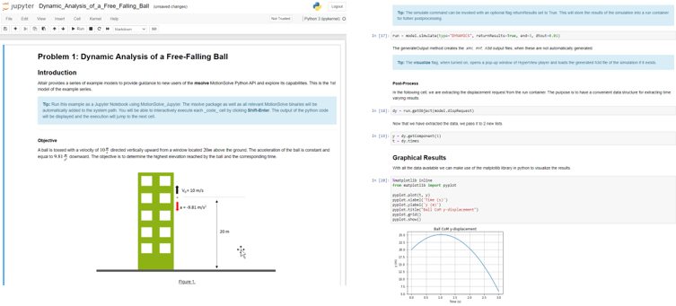
Figure 6.
Enhancements
- Updates to “Run with Live animation”
- The HyperWorks MotionView interface can animate the model on-the-fly
during simulation. This functionality has been further enhanced in this
release.
- Live animation works with MotionSolve co-simulation with EDEM and AcuSolve.
- Cname/Cunit is now supported.
- Resolved issues:
- Animation does not work when using single step forward/backward.
- Incorrect time in simulation failure message.
- Run failure with model containing outline graphics on Advanced Joint > Curve-Curve.
- Siemens MF-Tyre/MF-Swift Version 2212
- MF-Tyre/MF-Swift from Siemens, distributed with HyperWorks, is updated to Simcenter Tire version 2212 from version 2020.1.1.
- Cosin FTire Version 2022-4
- MotionSolve now supports the updated version of Cosin F-Tire 2022-4 used in the vehicle simulations.
- Option to Write Pre-2020 Style Label for Outputs in Solver Deck
- In version 2020, MotionView changed the way output labels are written to the solver deck so that the labels follow a consistent pattern for all output types. The change also influences the Request labels in plotting or any other post-processing tools that depend on the label patterns in the result files. A Preferences dialog option is now available ( in MotionView) to set the label to the pre-2020 style pattern.
- Default Settings
- The following default settings have been changed:
- Altair Compose/Activate OML under is On.
- Use in linearization option is On upon creation of a Solver Array of type Plant Input/Plant Output.
- Get properties from associated graphics option is On upon creation of a Body.
- Default value of maximum iteration under Static simulation settings has been changed to 750.
- Contact Pressure Contour Plot
- MotionSolve already calculates forces between bodies in contact. For this release, this feature has been expanded to include pressure distribution between contacting surfaces. In HyperView, the pressure distribution can be visualized using contour plots that are overlayed on top of the body's graphics. A contour plot is a graphical representation of a three-dimensional surface projected on a two-dimensional surface by plotting slices of constant values, called contours. For now, pressure distribution is supported for rigid bodies only. This feature may be expanded to flexible bodies in a future release.
Minor Enhancements
- Option to flip contact normals for a flexbody in contact is now available.
- All numerical values of XML files created during the SAVE command have been increased to 25 characters. This change ensures that the state and condition of the multi-body system after RELOAD is as close as possible to the ones before the SAVE. Hence, numerical errors and discontinuities in the time history are minimized.
- The version of the Parasolid packaged in MotionView and MotionSolve has been upgraded to 35.0.170.
- In the MotionSolve log file, error messages due to license checkout failures are more descriptive to support users in troubleshooting licensing issues.
- Support of xg, zg, xv, and zv attributes for the flexbody local coordinate system.
- A new analysis type called Verify instructs MotionSolve to verify the validity of an MBD model and provide model characteristics.
- Support for OML in MotionSolve custom functions.
- Support for deformable curve in linear analysis.
Known Issues
- In the new Tire component model, the variable PIN mode parameter, used to include a time variant expression to define the pressure value in a CDTire model, is currently not working.
- The soft-soil graphic system used to represent the soft-soil carpet road is not included in the new Tire component model. To represent the soft-soil road, use the new soft-soil deformable road or add the previous Auto Tire entity to include the carpet road.
- The visualization of the deformable road, tire force graphics, and air spring deformation is currently not possible using MotionView’s live animation. For such visualization, it is recommended to use the offline mode in the Run dialog and post-process the results in HyperView.
- Including a soft-soil deformable road in the model may impact the solver performance and result in a delay while writing result H3Ds based on the road dimensions and road increment. Only one road graphic H3D file should be active in MotionView while exporting the model to the solver.
- N-post analysis, Automated Report, and setting the road property file in the Events dialog are not supported with the new component; use the previous Auto Tire for such use cases.
Abaqus Solver Mode Deprecation
MotionView has been supporting export to the Abaqus solver deck for limited use cases. In version 2023, this solver mode is being deprecated. The Abaqus solver mode will not be available as a choice by default under . It can be turned on through the Preferences file.
Resolved Issues
- Application error when rapidly clicking Check Model twice.
- Icon for vector selection filter on the microdialog in the Marker's orientation context has changed for Dark Theme.
- Ground body Entity Editor shows contact prediction property.
- Flexbody pair sides in contact results in application error.
- Application error upon clicking unresolved Curve collector hyperlink in the panel.
- Flexbody graphic is not listed in the contact graphic dialog invoked from the Entity Editor.
- Application error when trying to merge bodies belonging to a rigid/ground group.
- Entity Editor is not displayed when you copy/cut/paste an entity.
- Plot and Animate buttons are not active immediately in the Run status dialog upon completion of a run.
- Vector created using CAD has incorrect origin.
- Vector cannot be picked using the Advanced selection dialog when invoked from the Orientation context.
- Expression Builder does not work for the Coefficient dialog in the ControlSISO Entity Editor.
- Reports are not readily available upon Live run.
- Microdialog hides when you enter a joint's context by double-clicking a joint.
- "Only interface nodes" status in Nodes/Modes dialog is not checked.
- Application error when adding a side of a flexbody pair in Contact.
- Application error when clicking on an unresolved hyperlink of a Curve collector in an Entity Editor.
- File menu closes unexpectedly when clicking the Solver interface.
- Belt pulley subsystem: In certain scenarios, belt wrapping at the end segment is incorrect.
- Craig Chang Contact method of CMS in FlexPrep works on Linux.
- Field entity > Stiffness and Damping matrices are transposed when exported to a solver deck.
- Show/Hide icon is not highlighted when in context.
- Entity Editor is not displayed after copy/cut/paste of an entity.
- Model containing multiple instances of the same flexbody, but with different interface nodes, fails to run in Live mode.
- CAD Import in HyperMesh failed when using the interactive mode in Linux.
- Application error due to space in the path when working with Activate co-simulation.
- Interface node cannot be picked for Points when there are coincident nodes.
- Space at the end of the Run name results in error during a Live run.
- Outline graphics on Polybeam results in an error during a Live run.
- Selecting NLFE Body in the Contact panel results in an application crash.
- System definition through *DefinitionInclude gets overwritten during the export of a system.
- Entity note in Output overwrites the title of the output in the solver deck.
- MotionView fails to find EDEM in Linux during geometry transfer.
- Component names are not filtered when PLT/NAM is read into a curve entity.
- MotionView crashes when invoking the Run settings when in the Orientation context.
- MSolve API for model.simulate(type=”Linear”) accidentally ignored user-defined attributes.
- Leaf Spring Builder not working on a web interface.
- Model with CDTire not working if saved and reloaded after static simulation.
- In some instances, an H3D generated by MotionSolve is not loading correctly in HyperView.
- During animation in HyperView, markers on flexible bodies are not moving correctly with the grid deflections.
Altair Multi Body Solutions 2022.2 Release Notes
Highlights
- Save Interval
- Run workflow updates
- Entity Editors
- Vector entity workflow
- Support for automatic simulation saves at specified intervals
- New Transfer Case with differential model added for 4WD vehicles in the Assembly Wizard
- IC engine powertrain model added for 4WD vehicles in the Assembly Wizard
- Locking differential system available for vehicles in the Assembly Wizard
- Road Tools performance enhancement
New Features
- Automatic Incremental Save
- You can now instruct MotionSolve to save the model and states during
simulation in specified intervals. Invoke this feature using the
Param_Simulation model statement by adding the
attributes save_increment and
save_inc_overwrite to the XML input file.
Automatically saving models is particularly useful for long simulations
of complex models and/or co-simulation with other solvers. If, for some
reason, the simulation or co-simulation gets interrupted, then
MotionSolve can restart a simulation from the last successful saved
state, instead of re-starting the simulation from the beginning.
Furthermore, you can branch off from a saved model/states and perform
model modifications and/or alternative analyses. Currently,
save_increment is only available for MotionSolve.
UI support in MotionView is planned for a future release.
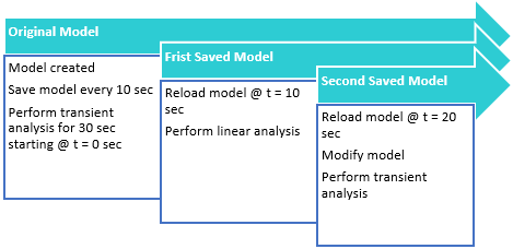
Figure 7. - New Transfer Case with Differential Model Added for 4WD Vehicles in the Assembly Wizard
- The Car/Small truck vehicle library in MotionView contains a new
Transfer case with a center diff model. This is located in option.
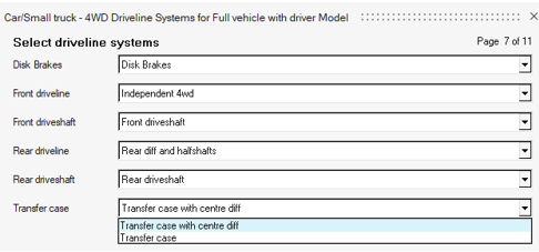
Figure 8. - IC Engine Powertrain Model Added for 4WD Vehicles in the Assembly Wizard
- The Car/Small truck vehicle library in MotionView contains a new option
for the IC Engine Friction Clutch (Manual) powertrain model for Four
Wheel Drive vehicles.
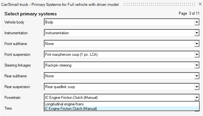
Figure 9. - Locking Differential System Available for Vehicles in the Assembly Wizard
- A new differential locking system was added to the MotionView Assembly
Wizard for Car/Small Trucks and Heavy Trucks.
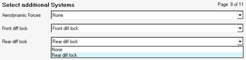
Figure 10.
Enhancements
- Run Workflow Updates
- The new Run workflow in HyperWorks supports co-simulation with EDEM. In addition, several issues related to solving models containing 2D contacts, deformable curves, and so on have been resolved.
- Entity Editor
- More entities have an Entity Editor in HyperWorks. Editors are now available for the SolverVariable, SolverString, SolverDiff, Outputs, Polybeam, and Vector entities.
- Vector Entity Workflow
- The Vector entity has also been enhanced to provide an origin for the
vector and graphic visibility. The vector can be oriented along an
existing point entity. In the HyperWorks interface, the vector entity
can also be oriented graphically.
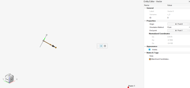
Figure 11. - Linear Sparse Solver
- At each Newton iteration, MotionSolve solves the linear systems of equations for , where is a sparse, unsymmetric Jacobian matrix, includes the unknown differences in states, and represents the right hand side. You can now choose between HARWELL, PARDISO, or user-defined sparse solver using SPARSESUB. The default solver is HARWELL; that works best in most applications. The type of linear sparse solver can be selected via the Param_Simulation command in the XML input file and is intended for advanced users only. There is no user interface support for this feature in MotionView.
- New Model Function - Distance
- MotionView has a new model function to calculate distance between entities. Syntax: distance(entity1, entity2).
- Road Tools Performance Enhancement
- The road files generated using the Road Tools are now saved as *.h3d files instead of *.obj files. This modification brings significant performance improvement related to road generation time, loading time, and output file size.
Minor Enhancements
- The default maximum iteration for the static solver has been increased to 750.
- In previous releases, the co-simulation was not able to take full advantage of EDEM running on GPUs. In this release, the coupling with EDEM has been enhanced such that EDEM can now better utilize the advantages of GPUs while co-simulating with MotionSolve.
- Flexprep: Craig-Chan-Contact is now supported on Linux
- The modeling statement Post: Graphic has been extended with a new clearance attribute for Triamesh graphics that allows you to superimpose clearance to the existing mesh. The clearance helps meshed graphics in contact with a tight fit to avoid friction and penetration due to the mesh discretization.
- MotionSolve includes the Conditional Numerical Reproducibility (CNR) from Intel® MKL on Windows and Linux. This feature allows MotionSolve to obtain reproducible floating-point results from run-to-run, even if the number of computational threads varies. This feature also improves the reproducibility from PC-to-PC, as long as they have the same architecture and operating system.
- Flexprep is enhanced to use a file for the interface nodes. A keyword argument, -INODESPATH, can be provided followed by a text file containing the node numbers as interface nodes.
- Batch co-simulation with EDEM provides a message if the EDEM installation cannot be found
Known Issues
- Live animation for flexbodies in the HyperWorks interface shows only the rigid movement of the flexbody. No deformation is shown. This issue will be addressed in a future release.
- Auto assignment of nodes for a flexbody during solver export may assign a coincident node at the interface node location and not the interface node itself. The workaround is to assign the nodes from the Nodes dialog in the flexbody entity.
Resolved Issues
- Properties in the compliant joint are not shown in the Entity Editor with multiple selection.
- Picked entity is not highlighted for Curve Graphic references when invoked from the Entity Editor.
- File graphic with locator data has incorrect settings for Auto Position and Orient option.
- Incorrect truncation of X data value more than 100 leads to curve visualization error.
- Reference collector in the guidebar for picking single entity allows picking paired entities.
- Application error when using the space bar on Derive from Graphics in the Body Entity Editor.
- Large loading time when loading a full vehicle model using large file graphics.
- A crash is observed when editing Notes for many entities together with the Entity Editor.
- Gravity dialog does not appear on Linux.
- MotionView does not report an error when a motion is applied on a compliant joint.
- Curve interpolation fails in some instances due to precision issue.
- Application error encountered when changing solvermode after adding an NLFE body.
- Application crashes while accessing the Materials dialog after clearing the model.
- Application error encountered in certain cases during co-simulation with FMU generated from MotionView.
- Cannot isolate graphics belonging to Ground Body.
- CM-Labs Vortex translator: Several translation issues are addressed.
- Flexbody with a different body coordinate system is not properly positioned when solved through msolve Py.
- Strain and Stress distribution in ANCF beams was not visualized correctly in HyperView.
- ARYVAL was not working after resizing a smaller Y Array used in GSE.
- FIM_S used to return mode 5 (static) even if a quasi-static simulation was running.
- There were some wrong and misleading component names in the *.abf file when the attribute ypr = True was used in the output requests of the MSolve-API.
- Saving and reloading a model with TriaMesh contact used to turn around all normal orientations such that the reloaded model fails.
- Automated report for Tire Envelope Analysis was showing the raw template statements. To see the report, you had to press the Evaluation Mode Control button in the TextView client. This is now fixed and no further operation is needed in TextView when plotting the report of the Tire Envelope analysis.
- AutoEntities were failing when specifying a curve data with only two points. The interpolation code was updated with the newest MotionSolve implementation.
- Support for simulation parameters in the leaf spring property file (*.lpf) is now available.
- Tire output requests showing non-zero values when AutoTires were deactivated in MotionView.
- A list of TNO roads no longer supported by Siemens (MF-Tire and MF-Swfit provider) was removed from the HyperWorks installation and a new set of roads, representing the same functionality, were included under Altair Roads <INSTALL_DIR>\hwdesktop\hw\mdl\autoentities\properties\Tires\ALTAIR_ROADS.
- Steering limit block in the Altair Driver File (*.adf) was not accepting the MIN and MAX steering values for open loop events.
- N-Post signal dialog showing compressed table and field options in high display resolution screens.
- Auxiliary Post graphics failing to display when being created in the N-Post event.
Altair Multi Body Solutions 2022.1 Release Notes
Highlights
- Flexbody Contact
- Entity Editor
- New Run Workflow
- Support for GPSTRESS
- Limited Multi-Threading
- CVT for Scooters
- Aerodynamics for Two-wheelers
- Slalom Events
- Tire Soft-Soil Obstacles
- Altair Driver Steering Control Using Torque
More details about these features, additional enhancements, and resolved issues are described below.
New Features
- Flexbody Contact
- MotionSolve supports 2D or 3D contact force between two bodies. In
previous releases, MotionSolve only supported contact for rigid bodies.
With this release, contact has been extended to CMS-based flexible
bodies. Whenever any rigid or flexible geometry on the first body
penetrates any rigid or flexible geometry on the second body, contact
normal and frictional forces are generated. The normal force tends to
repulse motion along the common normal at the contact point. The
frictional force tends to oppose relative sliding velocity at the
contact point. The contact force vanishes when the geometries no longer
intersect. New processes have been defined to account for flexbody deformation involving loads generated from general part-to-part contact or loads occurring around joint region. Those processes have been integrated into the flexible preparation tool FlexPrep.
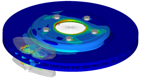 Figure 12.
 - Entity Editor
- MotionView’s new interface comes with an Entity Editor that lists the
entity properties to edit. In addition to what was available in 2022,
for 2022.1, the following entities now have an editor:
- Points, Bodies, Rigid Group, Markers, and Graphics
- Joints, Bushings, Spring Dampers, and Forces
- Couplers, Gears, Advanced Joints, and Contacts
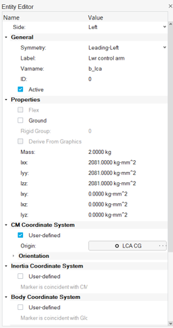 Figure 13.
 - New Run Workflow
- The new MotionView interface has an improved workflow for solving the
model through MotionSolve. The solution is carried through a live
connection to the solver through its msolve Python APIs. The new
workflow offers:
- Animation of the solution live as it progresses.
- Run status progress bar.
- Run history – Lists all runs submitted through the live process.
- Load results in HyperView and HyperGraph for detailed post-processing.
From the Analyze ribbon, select the Run tool.
- Support for GPSTRESS
- If the system contains a flexible body made of shell or solid elements,
the stresses of that body are usually evaluated by either printing or
contour plotting the element component stresses. However, element
stresses are calculated at the center and vertices of the elements. This
might not always be sufficient in cases where more accurate stress
values at the grid points are required. The grid point stress (GPSTRESS)
option in Altair OptiStruct offers you an alternative. GPSTRESS
calculates the stresses at the grid points from the adjoining shell and
solid elements.
For CMS based flexible bodies, MotionSolve supports the calculation of stresses on the grid points if the FlexH3D file contains grid point stress mode shapes. Grid point stresses must be explicitly requested in OptiStruct during the CMS analysis. The grid point stresses can be requested in the H3DOutput command statement (solver only). This option will be soon added to MotionView.
- Limited Multi-Threading
- The dynamic simulation in MotionSolve accounts for all the accelerations
(linear, angular, centrifugal, and Coriolis), forces, and constraints.
In other words, it solves the equations of motion in their most general
form, including nonlinear effects. This enables you to develop accurate
system level simulations of complex mechanical systems. At the core of most analyses, MotionSolve is solving a set of linear equations (A x = b). By default, a direct LU solver is utilized that is very robust and fast, but modest for parallel computation. Tests showed that most multi body models in MotionSolve perform best if up to four parallel threads are assigned. However, some models might benefit from more threads. By default, MotionSolve is now limited to four threads (nt=4), but the limit can be increased using the “nt” option.Note: A larger number for "nt" checks out more Altair Units for a single MotionSolve run. Please refer to the Altair Units Licensing documentation for more information on the solver unit draw.
- CVT for Scooters
- The Two-Wheeler Library in MotionView includes a CVT (Continuously
Variable Transmission) Powertrain for Scooter models. The Altair CVT
Powertrain is a mathematical formulation that represents an automobile
IC engine powertrain with CVT in the form of Control State Equations
(CSE).
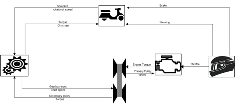 Figure 14. The CVT Powertrain can be included in the Full Scooter with Driver assembly model under the Two-wheeler assembly wizard library. With the possibility to design and control the parameters of the CVT Powertrain, this feature expands the capability of scooters modeling in MotionView, enabling a wide range of design evaluations and vehicle performance simulations.
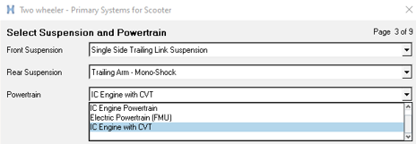 Figure 15.
 - Aerodynamics for Two-wheelers
- MotionView adds the option to include Aerodynamic Forces in motorcycle
and scooter models. The option is available in the Two-wheeler assembly
wizard library.
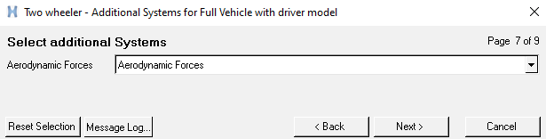 Figure 16.
 The aerodynamic parameters are entered in a Teim Orbit property file, *.aae, including environment parameter, wind velocity, side forces, drag, lift, yaw, and roll coefficients.
- Slalom Event
- MotionView contains an event to evaluate the performance of vehicles in
a slalom maneuver. The Slalom Event drives the vehicle in a sequence of
turns around cones in alternate directions measuring the vehicle state
variables, tire forces, suspension behavior, and other performance
indicators.
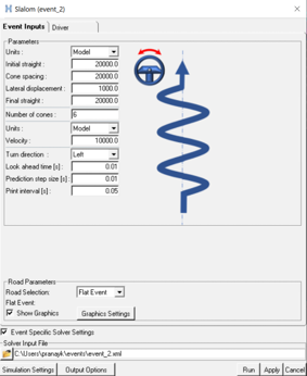 Figure 17.
 The Slalom Event is available for two-wheeler, car, and truck models using the Altair Driver. An automated Report template is available to simplify the post-processing of the simulation event containing the main output result plots.
- Tire Soft Soil Obstacles
- In the previous release, MotionView/MotionSolve included a new empirical
tire model for soft soil interaction to study the dynamic behavior of
vehicles traversing a compressible surface. The soil surface was
essentially flat, and an additional graphic was implemented to visualize
the tire sinking into the soft ground in the post-processing using
HyperView.
In this release, MotionView/MotionSolve enables the addition of obstacles to represent the compressible surface. A total of nine different obstacles can be included in the road property file: Rectangular, Circular, Bump, Ramp, Roof, Sine, Sine-sweep, Plank obstacle, and Crown obstacle.
The obstacles can be represented as soft soil with the same or a different surface material, or as a rigid obstacle. Figure 18. Note: The graphic used to visualize the soft-soil road can capture the obstacle's information only when the tire reaches its location. Rigid obstacles cannot be visualized in the post-processing graphic. This is a known issue that will be fixed in a future release.
 - Altair Driver Steering Control Using Torque
- In vehicles using leaning control (two-wheelers and three-wheelers), it
is now possible to perform the steering control using motion or torque.
The steering control using torque enables a smooth response of the
system. The selection of the steering control type is done in the Event
Editor under the Driver properties tab; the default selection is set the
Motion.
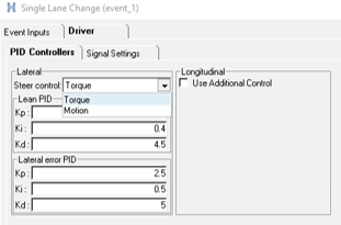 Figure 19. Note: The Steer Angle and Torque output request available in the Front suspension system of the Library models reports zero torque when the Steer Control type is set to Torque. For plotting steer torque in this case, it is advised to select: Driver outputs: Steer Torque – F2. This is a known limitation and will be resolved in a future release.
Enhancements
- Parameterize Existing Points with Respect to a Marker
- A new tool is available in the HyperWorks interface to define existing points relative to a marker. Using this option, independent points can be parametrized with regard to a marker, so that changing the marker’s position or orientation would also move the points. Right-click the context menu on selected point to display the tool.
- Parametrizing a Point to a Node
- A new location function, getnodecoordinates, can be used to parametrically link a point’s location to a node in the model. The node can belong to a flexible body or a graphic of type File Graphic. This function causes repositioning of such a point when the flexible body or the graphic is moved. When a point is created at a node (using Alt+Click) through the Point creation tool, the point coordinates are set using the getnodecoordinates function.
- Automatic Parsing of Windows Path into a Unix-equivalent Path
- A new environment variable, DOS_DRIVE_$, assigns a Windows drive letter to Unix paths. This creates a Windows-style path, starting with the drive letter, on Unix/ Linux. MotionSolve, while parsing any path, replaces the drive letter and colon ($:) with the content of the respective environment variable. This facilitates using input files (XML, PY) with references to other files (for example, H3D) containing Windows drive letters in Unix.
- Update to ProximitySensor
- The ProximitySensor element measures the minimum distance between the graphics or a mesh of two bodies. The sensor tracks the state of interference of the graphics and/or mesh, the length of the minimum distance, and the coordinates of a pair of closest points. In this release, ProximitySensor has been extended to flexible bodies.
- Updates to PTCV and PTSF
- The point-to-curve and point-to-surface constraints have been extended to support perpendicular constraint.
- Active State Python
- MotionView and MotionSolve support Python as a scripting language. Active State Python has been upgraded to version 3.8.10.
- Vehicle Control FMU Blocks Showing Only Relevant Parameters
- The FMU control blocks used in the vehicle dynamic simulations (EPAS,
TC, ABS, ESP, and Electrical Powertrain) were enhanced to expose only
the meaningful design parameters of the control unit. This facilitates
the understanding and the design modeling of the controls in the
MotionView environment.
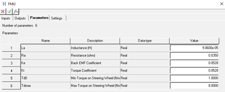 Figure 20.
 - New tutorial explaining how to add the Altair Driver in a generic model
- A tutorial is available in the Altair Simulation online help that explains how to include the Altair Driver control unit in a generic model created with simple entities and not using the Assembly Wizard library. The tutorial also demonstrates how to include a Slalom Event and add external control signals to the model.
Resolved Issues
- Definition-based entities fail to create using the Python API when path separator ‘\\’ is used.
- Contact model takes longer to export than previous versions.
- Spring graphics appear skewed when one end point has all coordinates with uniform scaling.
- The 'Create points at interface nodes' macro in the flexbody Nodes dialog does not work correctly when executed a second time.
- Graphics System collector does not allow picking using the Advanced selection dialog.
- “Show Spring” option on the Spring entity is not correctly exported to MotionSolve PY.
- An application error is encountered in the Data Summary's Spring Damper tab.
- Move tool – Snapping to mesh nodes using Alt key does not work.
- Move tool – Fails in the first attempt to grab the geometrical objects for move.
- Display of Compliant Joint is not proper in Topology View.
- MotionView does not allow export of flexbody without interface nodes.
- Application error when attempting to ungroup a rigid group containing grounded bodies.
- Application error when changing the variable name in the Entity Editor.
- Inconsistent invariants between OptiStruct and MotionView XML writer can occur in the FlexH3D if there is a MODEL card in FEM that reduces the model information.
- Linear analysis: Fixed an issue with the C matrix when POUTPUT has a force expression that is referring to BEAM, BUSH, or FIELD.
- Velocity motion with initial displacement has issues during an analysis after a static step.
- The error calculation for the controller in the Altair Driver steering motion control was improved to provide a smoother output torque signal in the steering joint.
- Altair Driver does not abort simulations when the demand path/velocity are violated.
Known Issues
- Model Identification Tool 2022.1
- In HyperWorks v2022.1, the Fit Monitor that shows the progress of the fitting process is not displayed. Use View Jobs to check the fitting jobs’ status. This issue will be fixed in a future release.
Altair Multi Body Solutions 2022 Release Notes
Highlights
- MotionView performance improvement
- EDEM coupling enhancements
- 2-wheeler stability event
- Tire soft-soil
- CDTire inflation pressure
- Tire test-rig - combined slip
- N-Post report
- Applus IDIADA proving grounds
- XenomatiX® scanned roads
More details about these features, additional enhancements, and resolved issues are described below.
New Features
- MotionView Performance Improvement
- MotionView core has been upgraded for improved model read and edit
times. Large assembly-based and systems-based models load up to 10 times
faster compared to previous versions. Similarly, exporting solver decks
of these models is also up to four times faster. There is a smaller
improvement time in reading CAD-based models.
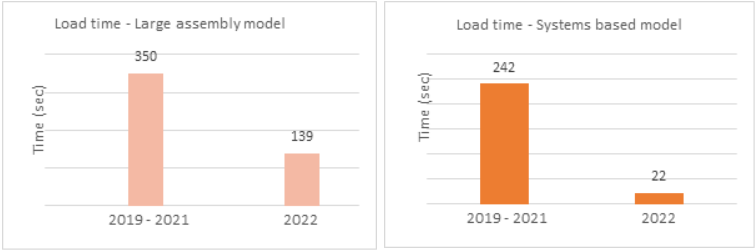
Figure 21. - EDEM Coupling Enhancements
- MotionView/MotionSolve can interface with Altair EDEM, a
state-of-the-art bulk material simulation tool. EDEM is based on the
Discrete Element Method (DEM) that simulates and analyzes the behavior
of bulk materials, such as sand, granules, capsules, grass, rock masses,
and so on. In this coupling, the mechanical part is modeled in
MotionView and the bulk material is defined in EDEM. Using MotionView,
you can transfer geometries directly to EDEM and initiate the
co-simulation between MotionSolve and the EDEM solver. New to this
release is the transfer of geometry labels from MotionView to EDEM.
Graphics in EDEM that are connected to bodies in MotionView/MotionSolve
no longer need to be named component_0000,
component_0001, and so on. This helps
significantly in associating EDEM graphics with MotionView/MotionSolve
bodies.Note: This feature works only with EDEM 2022 or newer.
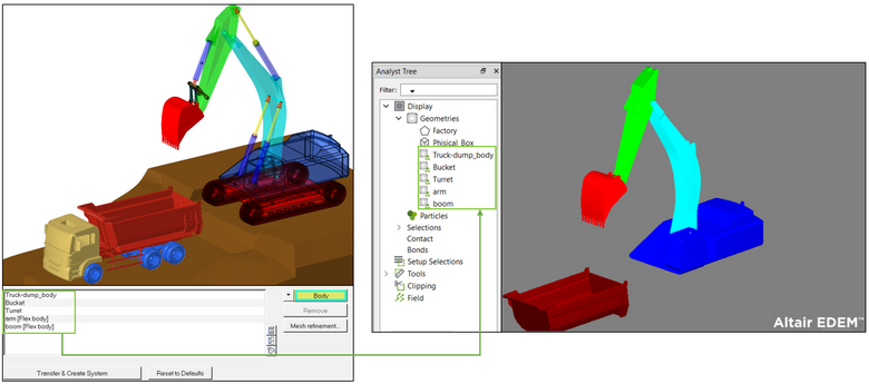
Figure 22.Furthermore, MotionSolve supports the Save/Load functionality for co-simulation with EDEM. You can save results in specified increments and restart at a saved point. The advantages are two-fold:- View intermediate results and adjust either the MotionSolve or EDEM model, if necessary.
- Co-simulations that were interrupted do not have to be restarted from the beginning, but can instead be restarted from a saved point in time.
- 2-Wheeler Stability Event
- A new event was added in MotionView to evaluate the stability of leaning
(especially 2-wheeled) vehicles. To help understand the weave and wobble
modes, the event can perform a Linear or Transient analysis, using a
pulse force or a general force defining the disturbance on the vehicle.
The vehicle can be simulated on different road surfaces. A report
session of the stability analysis includes:
- Linear analysis: Animation of the event and eigenvalues reported by MotionSolve for the model (.eig file).
- Transient analysis: Animation of the event, applied pulse or disturbance, steering wheel angle, FFT magnitude of the steer angle, roll angle, FFT magnitude of the roll angle, yaw angle, and FFT magnitude of the yaw angle.
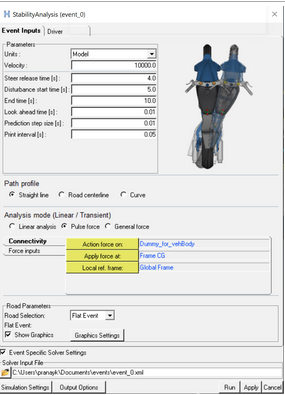
Figure 23. Stability Event for 2-wheelers - Tire Soft-Soil
- MotionView/MotionSolve offers a new empirical tire model for soft soil
interaction. It offers a computationally efficient way to study the
dynamic behavior of vehicles traversing a compressible surface. The soil
is characterized by the well-known equations proposed by Bekker and
Wong. An additional graphic was implemented that visualizes the tire
sinkage into the soft ground. You are encouraged to use this tire model
first for initial design study before engaging in a more complex and
computationally expensive MotionSolve, EDEM, and PME FlexTire co-simulation.
Figure 24. Tire Soft Soil Post-processing in HyperView - CDTire Inflation Pressure
- A new field was added in the AutoTire panel to include the inflation pressure for CDTire models. With inflation pressure, you can simulate the effects of a tire blowout or flattening during a vehicle simulation.
- Tire Test-Rig - Combined Slip
- In MotionView, the Tire Test-Rig option simulates the combined slip
test. This test help evaluate the limits of the tire model in events
where it is subjected to multi-directional forces. A report session of
the combined slip test includes the model animation, tire force plots,
slip values, and cross and normalized plots.
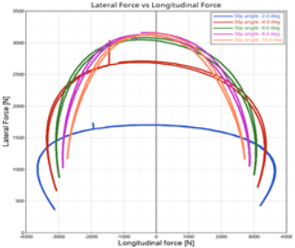
Figure 25. Cross Plot: Lateral Force vs. Longitudinal Force - N-post Report
- A results report is available to simplify the post-processing of the
n-post test rig, assisting the analysis of vehicle vibrations or loads
evaluation. The report opens a list of pages and windows in a HyperWorks
session, displaying the animation of the event, vehicle body
accelerations, steering wheel accelerations, wheel forces, actuator
displacements, and actuator forces.Attention: Known issue - Overlaying of an n-Post report is not supported in this release.
- Applus IDIADA Proving Grounds
- Applus+ offers services and solutions in the testing, inspection, and
certification sector. At the IDIADA headquarters in Spain, there is a
370-hectares proving ground with various test tracks. The virtual
representations of these test tracks are available to be used as road
models in MotionView/MotionSolve simulations. The road files are
extracted from high resolution scans to capture all macroscopic
unevenness and irregularities of the real surfaces. The road files are
available through the Altair
Partner Alliance. You can accelerate their vehicle design and
development activities by integrating IDIADA Spain Virtual Proving
Ground (ISVPG) directly into your MotionView/MotionSolve model.
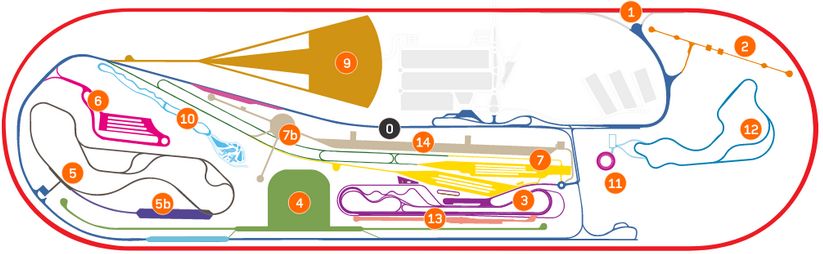
Figure 26. Applus IDIADA Spain Virtual Proving Ground - XenomatiX® Scanned Roads
- XenomatiX® measures and collects data of any road network or part of it, including local roads, highways, harbor quays, airport runways, or even off-roads. The data is measured using the solid-state lidar sensor XenoTrack and analyzed in XenoWare road software. A sample set of scanned road data from XenomatiX® are now available to be used as road models in MotionView/MotionSolve simulations. The road files are available through the Altair Partner Alliance.
- MotionSolve Online Community
- Altair hosts an online community of experts to share insights and collaborate with the wider CAE community. Part of this community includes forums and user groups where you can obtain answers to questions with support from other users. Click here to access the MBS Solutions community. MotionView/MotionSolve users are encouraged to participate in this forum to engage in online discussions, obtain insightful use cases, and access valuable resources to discover, learn, and grow as a MotionView/MotionSolve user.
- HyperWorks Startup Dialog
- In the Windows Start menu, individual client shortcuts are replaced by a single HyperWorks shortcut that prompts you to pick the client, profile, directory, or recent models and sessions.
Enhancements
- In MotionView, you can export a flex body to the solver deck without any connections.
- The flexible body preparation tool (Flexprep) reads OptiStruct FREE format statements in the FEM input file.
- The Preload tab in the SpringDamper panel is deactivated when stiffness or damping have non-linear properties.
- MotionView provides clearer error message upon failure of geometry transfer to EDEM. A warning message is displayed during the transfer of geometry to EDEM if the EDEM DLL path has a mismatched version.
- Export to CM Labs Vortex supports transferring rigid groups.
- New options to control Preload for SpringDampers are available.
- Using component names and units (cnames and cunits) are supported for user-defined outputs.
- MotionSolve added an optional attribute to the point-to-deformable-curve constraint (PTCV) that enforces the z-axis of the point marker to be either normal or tangential to the curve.
- MotionSolve relies on the industry-wide accepted Intel® Math Kernel Library (MKL) for its math routines. These routines are highly optimized and threaded for maximum performance. With this release, MotionSolve upgraded the version of the MKL from 2019.5 to 2020.
- MotionSolve’s Python-based API MSolve supports MQTT, a publish-subscribe network protocol that transports messages between devices.
- Tire deformation for CDTire and F-Tire can be visualized in HyperView.
- Aerodynamics force is added to the truck libraries.
- Fiala tires have the option to enter the tire friction (Mu) curve as a function of slip or force.
- MotionSolve supports F-Tire version 2021.4.
- MotionSolve supports OpenCRG version 1.2.
Resolved Issues
- mdl_batch fails launching HyperMesh when executed from a non-writeable location.
- Cell heights for tables in datasets were inadequate.
- Isolating entities on vehicle models breaks Autotire and AltairDriver.
- Application error is observed with degree of freedom check when Motion entity is unresolved.
- H3D file reference in exported MotionSolve solver deck (Python-based API) has changed to the absolute path.
- Application error while creating multiple systems using the Belt-Pulley system creation tool.
- An error is encountered during data MDL import relating to the number of records in Table Form.
- Export to Vortex Studio created an untitled folder under the user’s home directory.
- Flexbody ID assignment process on clicking run breaks shared definition.
- Application error when transferring model containing grounded bodies to Vortex.
- Initial conditions tab in Systems panel does not list bodies whose ICs are overridden by individual body IC assignment.
- Erroneous inertia properties are reported for certain surface-only graphics.
- Importing a system definition into a system with the same definition name results in an application error.
- An application error is encountered in the tab.
- In certain instances, a root-finding issue for CVCV constraint can occur.
- In some cases, using AltairDriver results in incorrectly stacked licenses.