EDEM Cal
EDEM Cal is a utility which works with EDEM and is designed to assist users in performing calibration. It removes manual steps from setting up and running multiple EDEM simulations. EDEM Cal can create and submit parameter space searches automatically. EDEM Cal collates automated results from EDEM analysis and supports the use of EDEM Py scripts to obtain results, significantly reducing engineering time needed. At the moment EDEM Cal is a windows only application, but can generate a batch job for Linux.
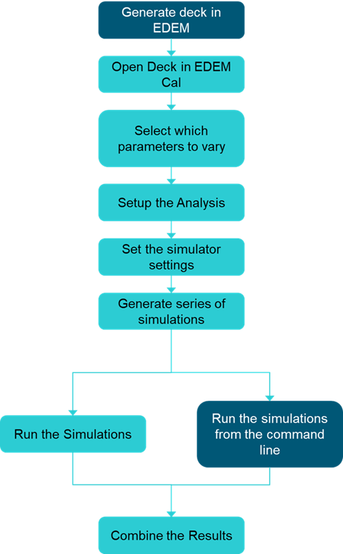
The workflow for EDEM Cal can be seen below:
EDEM Cal Interface
The interface in EDEM Cal consists of a Menu bar (1) and a Toolbar (2), indicated in figure 1.
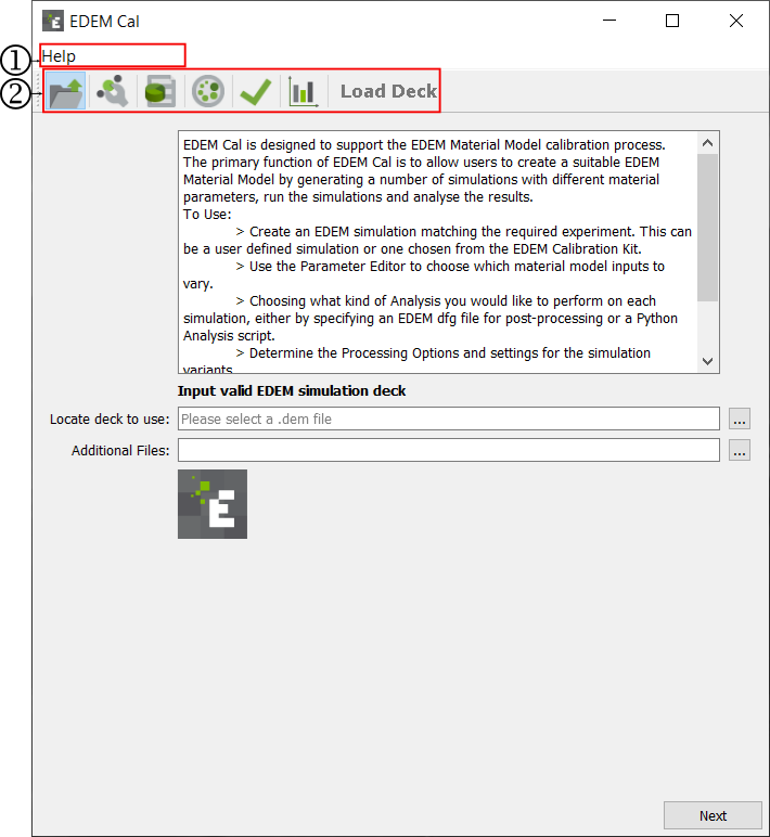
Figure 1-The EDEMCal Interface
The Menu bar contains:
- Help: Shows the details of the EDEMCal software
The Toolbar contains icons to change the User Interface to generate EDEM simulations, execute the simulations and compile the results. To find out more about each one, click on the corresponding text in the action column below.
|
Icon |
Action |
|
|
|
|
|
|
|
|
|
|
|
|
|
|
|
|
|


Load Deck
The first step of Setting up a calibration run is to load in a prototype EDEM deck. This deck should be set up in such a way that they can all be run from the command line. The Load Deck is the first page visible in EDEMCal. The Interface can be seen below:
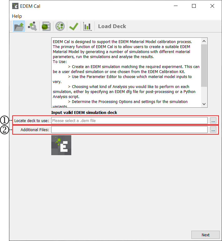
-
Insert path to the EDEM deck.
-
Select the additional files required to run the simulation.
Selecting an EDEM deck
The .dem file associated with the EDEM deck needs to be used for EDEMCal. This can be written or pasted into the box or found through the windows explorer interface. To find the file in windows explorer click on the "..." button. Navigate to the deck and select open. This will populate the box with the path to the .dem file.
Additional Files
Any additional files required to run the simulation from the command line must be select. When importing multiple additional files - highlight multiple files in file explorer and then add. Example additional files include coupling scripts, preference files and API .dll or .so files.
Parameter Editor
Once the Deck is loaded you can modify the parameters. The parameters which can be modified are:
-
The particle-particle interactions
-
The particle-geometry interactions
-
The physics model parameters and options
Note: not all of these parameters need to be varied, any parameters not selected will run with the original value defined in the prototype simulation.
The Parameter Editor can be seen below:
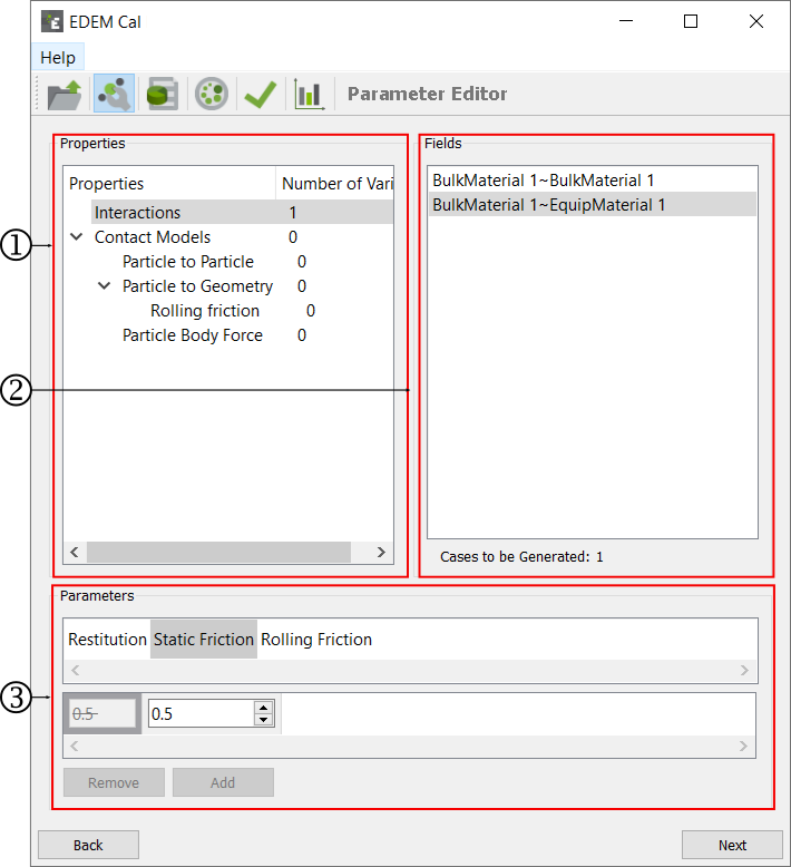
The Properties section
The Properties section is populated depending on the settings in the prototype simulation deck. The interaction option will allow users to modify the parameters defined in the Interactions Properties of the Bulk Material and Equipment Material interface of EDEM. The Contact Models section allows users to modify the parameters defined in the Contact Model specified in the prototype simulation deck. EDEM Cal does not allow users to change the Contact Model specified in the prototype simulation deck.
When a Parameters is selected to be modified the "Number of Variances" column will be updated to indicate how many values will be changed.
The Fields section
Selecting a property in the properties section will populate the Fields section. The Fields section allows you to select the specific interaction to be modified or a setting in the Contact Model. For interaction based parameters the specific bulk material-bulk material/equipment material combination is listed.
The "Cases to be generated" value is updated depending on the number of parameters varied. This is the number of combinations from the parameters selected to be modified by the user.
The Parameters section
Once a property and field has been selected the Parameters option will be updated. This will be reflective of the current value in the prototype deck. There may be more than one parameter which can be changed. Selection the appropriate parameter will allow you to vary that specific parameter. Clicking the "Add" option will discard the original value and instead use the newly defined value. It is possible to add multiple values in this interface. Selecting a value and clicking remove will delete a value. By default adding a new value will overwrite the original value, there is no need to remove that value. To include the original value in the calibration re-add that value to be used in the calibration.
Post Processing
EDEM Cal allows for automated post processing of the simulation to be performed. This can be based upon:
- A pre configured data query from the EDEM analyst
- An EDEMPy script
The Post processing interface looks as below:
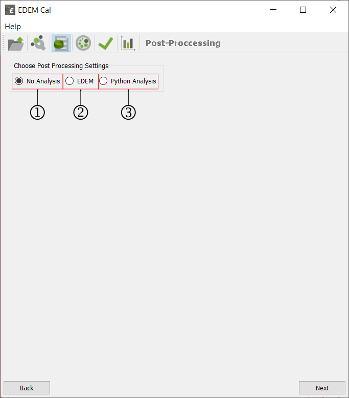
-
No Analysis
-
EDEM
-
Python Analysis
No Analysis
A manual, or alternative approach for analysis can be used. In such instances no post processing options will be required from EDEMCal. Selecting the "No Analysis" option will mean that simulation are set up and simulated but no post processing will be performed.
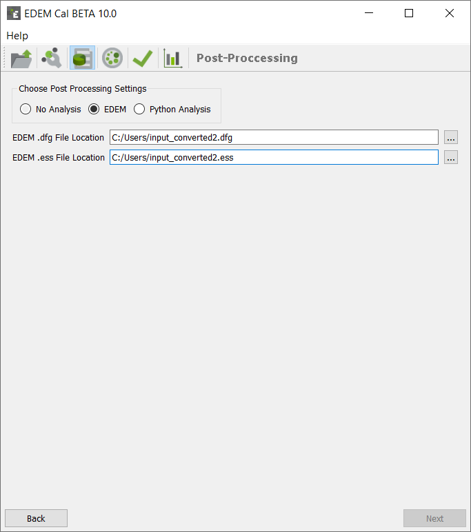
EDEM
- The EDEM option allows users to use a predefined query within the EDEM Analyst to analyze the each of the simulations performed by EDEMCal. In order to perform this Analysis the query must be compatible with the EDEM prototype deck. The EDEM simulation should be saved and closed.
- The EDEM Configuration file (.dfg) contains the analyst settings. This can be written or pasted into the box or found through the windows explorer interface. To find the file in windows explorer click on the "..." button. Navigate to the dfg and select open. This will populate the box with the path to the .dfg file.
- The EDEM Data file (.ess) contains information on bin groups. If the analysis performed contains bin groups the .ess file will be required in addition to the .dfg file. This can be written or pasted into the box or found through the windows explorer interface. To find the file in windows explorer click on the "..." button. Navigate to the ess and select open. This will populate the box with the path to the .ess file.
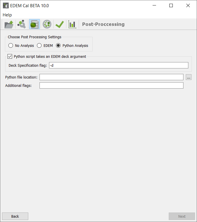
Python Analysis
A EDEMPy script can be used for the post processing. For more information on running EDEMPy analysis please visit the EDEM User Forum.
- Deck specification flag: -d (or similar to what is in the script)
- Python file location: input path to the .py file.
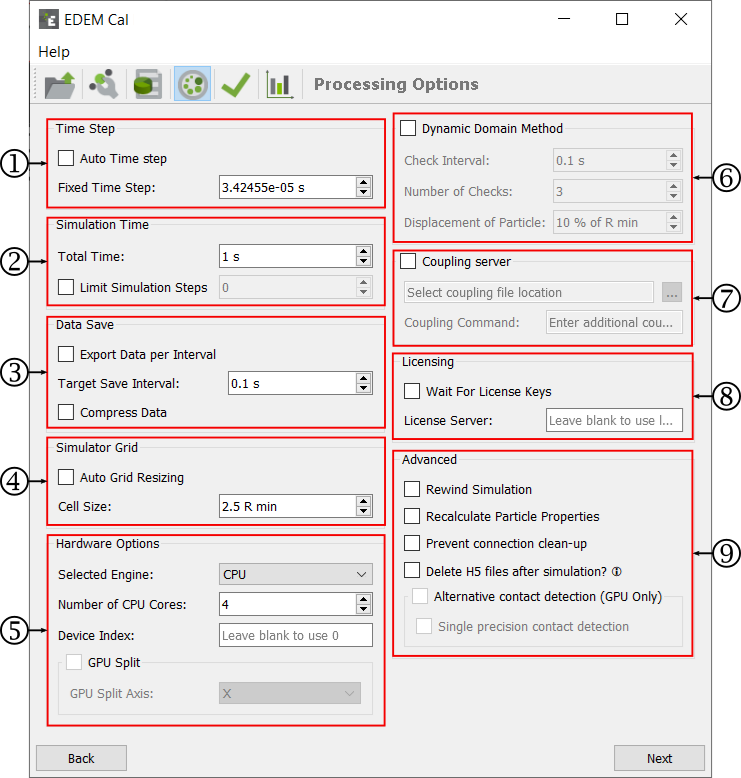
Processing Options
The processing options are used to determine how each simulation will run.
-
Time Step
-
Simulation Time
-
Data Save
-
Simulator Grid
-
Simulator Engine
-
Dynamic Domain Method
-
Coupling Server
-
Licensing
-
Advanced
Time Step
The time step is the amount of time between iterations (calculations) in the Simulator. The time step is either fixed and remains constant throughout the simulation or the Auto Time Step option can be chosen.
-
The value is displayed as the actual time step (in seconds).
-
Auto Time Step: If this box is ticked EDEM will automatically adjust the Rayleigh Time Step to the smallest radius that is currently in the simulation rather than the smallest radius to be created. It uses 20% for this particle size. For example, a simulation that has 10 mm particles from t=0s and 3 mm particles from t=3s will use 20% of the Rayleigh Time Step obtained with 10mm until time 3s, when it would be updated to the Time Step value obtained with 3mm.
Information on choosing an appropriate time step can be found here.
Simulation Time
The simulation time is the amount of real time your simulation represents.
- Total Time: The total actual length of the simulation in seconds or minutes.
- Limit Simulation Steps: Run the simulation for a given number of steps.
Data Save
- Export data per interval: Exports data per write out interval during simulation.
- Target save interval: Write out interval for saving EDEM data.
- Compress data: Enable of disable data compression on saving. Compressing data saves space however it can result in longer simulation run times.
- Simulator Grid
EDEM calculates the smallest particle size in the simulation (Rmin), the user then sets a grid cell size based on this particle size. 3 Rmin is the default value, typical ranges are 3-6 Rmin, the Estimate Cell Size option provides guidance on the optimal Cell Size for a specific simulation time step. The grid does not impact the simulation results, only the simulation speed. A smaller grid size results in more memory (RAM) usage; reducing the grid cells size below 2 Rmin can result in a significant slow-down for the simulation.
The Cell Size can be manually entered or Automatically set based on the Auto Grid Resizing, which determines the grid size based on the simulation and the available computer memory.
Simulator Engine
The Simulator Engine has options similar to those in the EDEM interface. These are:
- Selected Engine
- CPU
- GPU
- The Number of CPU Cores. This is the number of cores per simulation
- Device index. This is used to determine which GPU card should be used for the simulation. To determine the device index open EDEM>Tools>Options>Simulator Engine. The Device index is listed next to the name of the device. Alternatively this can be determined from the command line.
- GPU Split. If you are using mGPU then select an axis to split the simulation.
Dynamic Domain Method
If using the Dynamic Domain the Check Interval, Number of Checks and Displacement of Particles must be entered.
Coupling Server
If running the simulation using the Coupling Interface tick the Coupling server option, any additional inputs for the coupling should be added to the coupling command text box.
Licensing
If the simulations should be run using licenses from a specific licensing server these can be entered here. Selecting the Wait option will mean that if licence keys are not available the simulation will wait until such times as they are available before continuing.
Advanced
Additional parameters can be turned on or off using these tick boxes. These parameters are explained here.
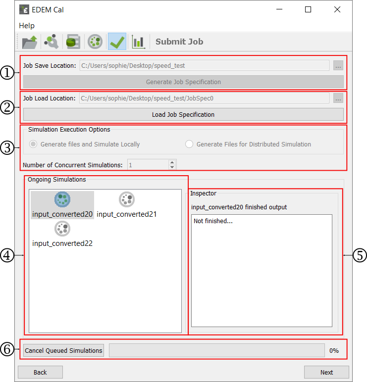
Submit Job
-
Job save location
-
Job load location
-
Execution Options
-
Ongoing Simulations
-
Simulation Inspector
-
Simulation Start button
Job Save Location
The Job Save location is the computer location which is used to generate all of the decks and the necessary files required to run the simulations. This can be written or pasted into the box or selected through the Windows Explorer interface. To find the file in Windows Explorer click on the "..." button. Navigate to the folder and select "select folder". This will populate the box with the path to the that folder.
Once populated click on the "Generate Job Specification" button.
This will generate all of the decks in appropriate folders as well as the Job Specification. The Job specification gives a summary of all of the parameters varied and simulator settings.
Job Load Location
The Load Job specification option is used to recover previously generated job specifications. To find the file in Windows Explorer click on the "..." button. Navigate to the folder and select "select folder". This will populate the box with the path to the that folder.
Once populated click on the "Load Job Specification" button.
Execution Options
There are two options for running the simulations:
- Generate files and Simulate Locally: All decks are made as per the job specification, a batch file to run each one is generated.
- Number of Concurrent simulations: Specify the number of simulations you want running at the same time.
- Once selected select "Start Simulating"
- Generate Files for Distributed Simulation: All decks are made as per the job specification, a batch file to run each one is generated, but options to run locally are disabled. This is intended to be used when simulations will be run elsewhere, for example a Linux cluster.
Ongoing simulations
When simulations are running icons to display which simulation are running, finished, failed or queued are displayed. Clicking on icons representing completed or failed will show the console log for that simulation in the Inspector box.
Results Analyst
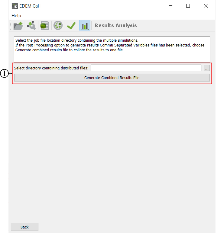
The Results analysis section of EDEM Cal combines all the results files into a single csv file. To generate this .csv file:
- Click on the "..." button. Navigate to the folder and select "select folder". This will populate the box with the path to the that folder.
- Once populated click on the "Generate Combined Results File" button.