Block Category: Time Delay
Inputs:
•b: Real scalar
•x: Real, complex, or fixed-point scalars, or vectors or matrices
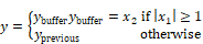
Description: The unitDelay (1/Z) block specifies a clocked unit delay. The input connector tabs are marked b (for Boolean clock) and x (for main signal). When the Boolean clock does not equal zero, the value contained in the single element buffer is copied to the block output (where it holds this value until the next non-zero Boolean clock). The current value of the main signal is stored in the unit buffer.
The unitDelay block is intended for modeling a digital delay in a continuous simulation. A typical digital delay is modeled by wiring a pulseTrain block or a constant value 1 (triggers at every time step) to the Boolean input connector tab on the unitDelay block. Use the timeDelay block to model a continuous delay.
If your system contains unitDelay blocks and you want to perform frequency domain analysis, substitute the unitDelay blocks with discrete transferFunction blocks.
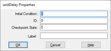
Checkpoint State: Contains the value of the unit delay at the checkpoint. If you have not checkpointed your simulation via the System > System Properties command, the value is 0. You can enter a value as a C expression.
ID: Reserved for future use.
Initial Condition: Sets an initial value for the output signal. The default is 0.
You can enter the initial value in scalar or vector notation. The initial condition matrix will set matrix dimensionality for the block. You can enter a value as a C expression.
Label: Indicates a user-defined block label that appears when View > Block Labels is activated.