After solving the Three_Spheres_VPol_MoM.cfx model, the
post-processing is done in POSTFEKO using the
PF_ISAR.lua macro.
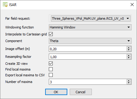
The PF_ISAR.luaapplication macro uses the following input parameters:
Far field request
Select the RCS far field request to process.
Windowing function
Hamming
Dirichlet
Bartlett
Blackman
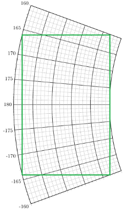
Interpolate to Cartesian grid
The 2D FFT requires that the X and Y distances should be uniformly spaced.
The basic ISAR implementation assumes that the angle range is small enough
such that the polar sampling approximates a Cartesian grid. The small angle
range assumption can be relaxed by transforming the polar grid to Cartesian.
This reduces smearing and shift of the scattering points and increasing
accuracy of the resulting ISAR image.
Figure 1. Polar to Cartesian transformation.
Component
Specify which E-field component to use to generate the ISAR result.
Supported options are:
Theta
Phi
LHC (Left Hand Circular)
RHC (Right Hand Circular)
Image offset
Offset distance of the ISAR image above the plane wave workplane.
Resample factor
Factor used to up sample the image resolution to create a smoother image
with more points. Note it does not change the underlying image resolution
based on the frequency and angular information.
Create 3D view
Generates a normal view of the partially transparent ISAR image with RCS
data displayed in dB.
Find local maxima
Calculates the specified number of local maxima in descending order in the
ISAR image.
Export local maxima to CSV
Export the specified number of local maxima to a CSV file. Find
local maxima has to be checked for this to work.
Number of local maxima
The number of local maxima to find.
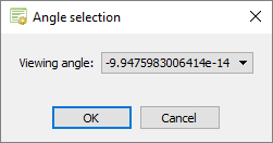
After accepting the input from the main form, the application macro
will process the RCS data and display a dialog to select the viewing angle from the
list. The default viewing angle is the average of the start angle and end angle.
Note: A
different viewing angle could reduce the maximum angular data range.
Figure 2. The Angle selection dialog for specifying the viewing
angle.
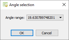
With the viewing angle specified, the application macro will
calculate the maximum angular range that can be used. The user can then select an
angular range from the list.
Note: The angular range affects the cross-range
resolution.
Figure 3. The Angle selection dialog for specifying the angular
range.
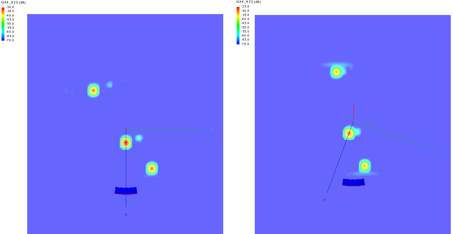
The ISAR images associated with the XY_plane and UV_plane solution
configurations are shown below. For this example, a resampling factor of 2 was used with
default values for the rest of the input parameters.
Figure 4. ISAR image (3.5 m x 3 m) obtained from the XY_plane solution
configuration (left) and the UV_plane solution configuration (right).
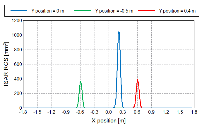
The ISAR dataset can also be used to generate 2D graphs, such as the image below showing
the RCS versus X position corresponding to each sphere’s Y coordinate.
Figure 5. RCS versus X position for the Y coordinates of points A1,
A2 and A3.
 Hamming
 Dirichlet
 Bartlett
 Blackman