Applying an Anisotropic Dielectric to a Region

Apply an anisotropic dielectric to a face bordering free space or dielectric region.

Note: When using the FDTD solution method, the anisotropic medium orientation is defined in the global coordinate system. For FEM, the orientation can be defined in a local coordinate system.
  1. Define an anisotropic medium.
  2. Select the region where you want to apply the anisotropic dielectric.
  3. From the right-click context menu, select Properties.
  4. On the Region properties dialog, click the Properties tab.


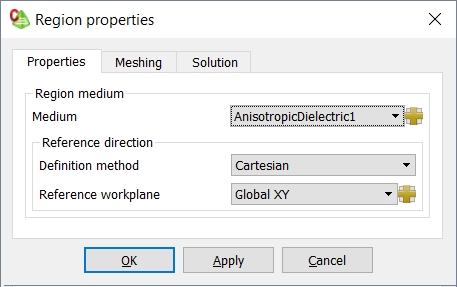
    Figure 1. The Region properties dialog (Properties tab).
  5. In the Medium drop-down list, select the layered anisotropic that you want to apply to the face.
  6. In the Definition method drop-down list, select the coordinate system in which the medium orientation is defined (only for FEM solution method).
    • Cartesian
    • Cylindrical
    • Spherical
  7. In the Reference workplane drop-down list, select the workplane in which the medium orientation is defined.
  8. Click the OK to apply the anisotropic medium to the region and to close the dialog.