Adding a PCB Source

Apply impressed line currents in the model to represent a printed circuit board (PCB). The impressed line currents are equivalent to the current values calculated for the traces and vias of a PCB.

  1. On the Source/Load tab, in the Equivalent sources group, click the  PCB icon.


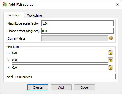
    Figure 1. The Add PCB source dialog.
  2. In the Magnitude scale factor field, specify the scaling factor.
  3. In the Phase offset (degrees) field, specify the phase (in degrees) to be added to the phase of the currents.
  4. In the Current data field, specify the PCB current data to be used to define the PCB source.
  5. In the Position field, specify where the source is to be placed.
  6. In the Label field, add a unique label for the PCB source.
  7. Click the Create button to create the PCB source and to close the dialog.