SimLab mesh export workflow
Introduction
This section presents the steps to follow in SimLab 2017 to export the mesh in a Nastran file.
Preliminary
- In SimLab, contrary to HyperMesh, all the operations (geometry, verifying …) are applied to the mesh and not to the geometry. The CAD import allows only to visualize the geometry. So, the first step is to mesh in surface. The volume mesh is done at the end.
- To open the help, press the key F1. The help will be opened on the page concerning the active command.
Workflow
- Open SimLab
- Import the geometry CAD
Two CAD imports exist:
-
:
It allows using the native format (Parasolid, Step, CATIA, ProE…). But the associated software must be installed
-
:
It converts and imports the native formats in Step or ParasolidAttention: The conversion can generate geometrical errors.
For this import, it is truly advised to choose the conversion in Parasolid: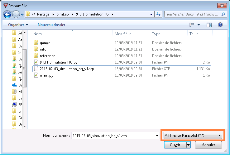 It gives access to automatic assembly option Imprint solid bodies which has to be checked at the import:
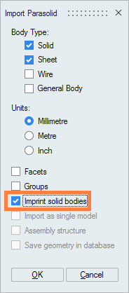 After the import, the components are visible in the data tree. If each component faces define a volume, then the following icon appears:
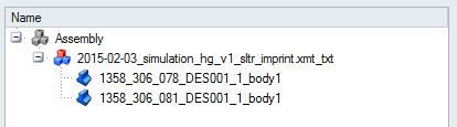 If faces don’t form a volume, the following icon appears:
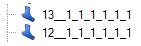
-
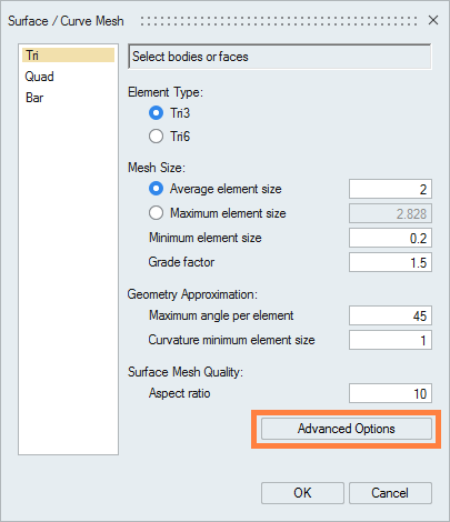
- Mesh the geometry faces:(in 2D Create)
- Select in the data tree the components to mesh
- Choose the mesh order (Tri3 for the first order and Tri6 for the 2nd order)
- Choose the mean element size. The value will be applied to all
the entities without "mesh controls"Attention: If the value is too high, the geometry can be misrepresented.
- In Advanced Options check the option
Imprint meshing allowing the
management of mesh conformity:
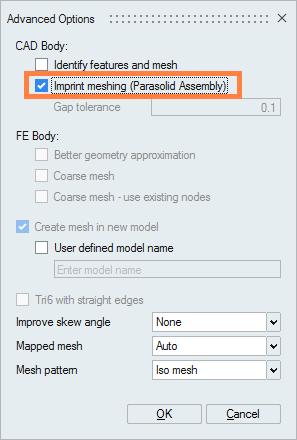
- Click on OK to mesh
The old geometrical components are made invisible, and new components of mesh type are created and visible in the data tree: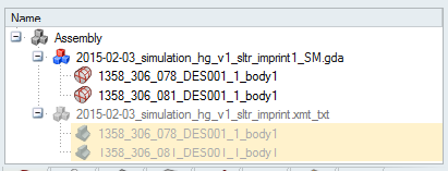
All the operations will be applied on those mesh components
- Most of the components which have a contact face will be assembled to obtain
a conform mesh, thanks to the option presented before.
If there are components which are not assembled, it is possible to do it manually.
-
Use the command Join:
(in Connect)
- Check the option General faces to join all
type of faces:
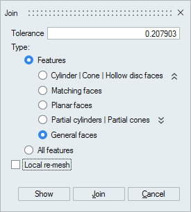
- Click on Show to visualize the faces to join, and then Join
-
Make a re-mesh of all the components to re-mesh correctly the contact area (with the same mesh data as the first mesh):
(in 2D Create)
Note: In the case of a component inside another one, use the command Boolean:(in Connect)
-
- Check the mesh:
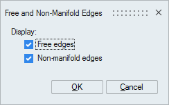
- (in Verify)
This command allows verifying if the mesh contains free edges (a free edge is an edge belonging to only one surface element) or non-manifold edges (belonging to more than 3 surface elements. This is authorized only in case of internal/shared faces).
- (in Verify)
This command allows verifying the intersections between elements
In case of defaults, several tools can be used to correct:- (in Modify) to fill holes or cracks
- (in Modify) to create missing surface elements
- Etc.
- (in Verify)
- It is possible to create the air box in SimLab or in Flux.
If you want to create the air box in SimLab:
-
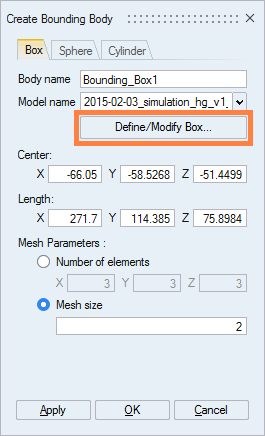
Choose the bounding box shape (Box or Sphere or Cylinder)
Here we choose Box shape
- Click on :
- Check Bodies:
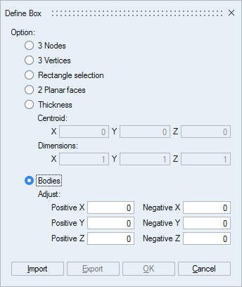
Then select all the components (left click). The box appears: it is possible to move a face directly on the graphic (to extend or reduce the box size)
- Validate
-
Define element size Mesh size or elements number Number of elements of the bounding boxAttention: Choose a value close to the value entered for the device (to allow the mesher connecting the elements).
- Validate
A new mesh component Bounding_Box1 is created: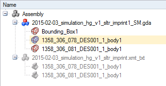
-
- Prepare the project for volume meshing:
-
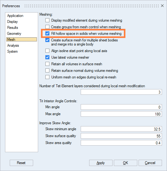
Verify in the preferences that the option which allows meshing the holes inside a volume is activated:
:
check Fill hollow space in solids when volume meshing:
- If the bounding box "Bounding_Box1" is not in the same node (in data tree) as the device component, make a drag&drop to the same node
-
To have a conform mesh, make a Merge+ of all the components (including bounding box):
(in Body)
Only one component exists in the data tree: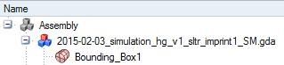
-
- Mesh the component in volume:
(in 3D Create)
- Select the mesh order (TET4 for first order and TET10 for second order)
- Define the mean element size
- Choose the volume mesh Internal grading coefficient (1.2 corresponds to a low grading, 2 to a high grading)
- Choose the Quality criteria
(Stretch or Aspect
ratio or …)
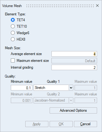
- Validate the volume mesh
-
Make a Merge– on the component:
(in Body)
The initial components appear: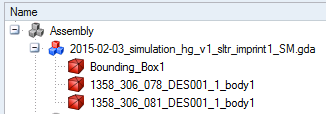
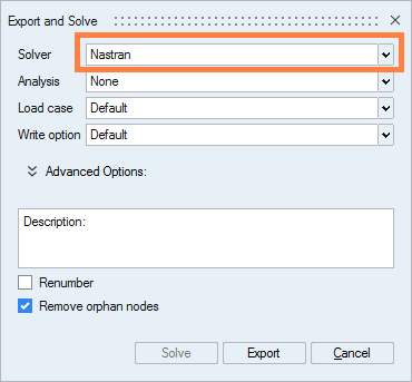
- Export the mesh:
- Select the components
- Choose the Nastran solver:
- A message asking if you want to create and assign properties to
components appears: click on Yes:
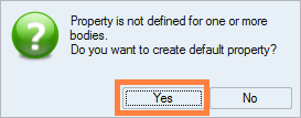
That allows distinguishing the volumes in Flux
- Choose the name of the .bdf file to export
Note: The option Renumber can be checked if the file would contain high elements numbers (for example if it is a little part of a large size device).