Workflow with "Layers" Mesh Generator
Introduction
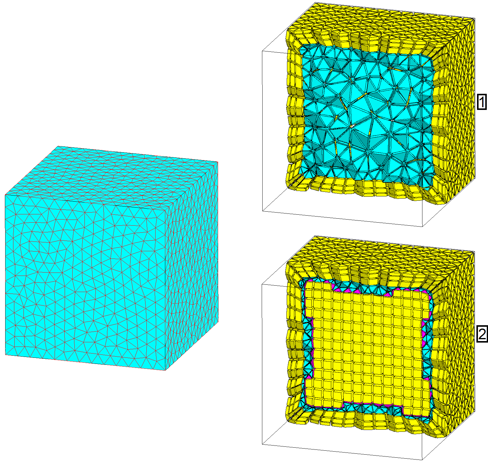
The main workflow advised for the skin effect mesh based on a specific mesh generator called Layers is presented here.It is based on "MeshGems-Hybrid" module of Distene. It gives a mixed mesh elements types (it creates hexahedra, prisms, pyramids, or tetrahedra).
It allows to mesh the boundary of volumes in layers with extruded elements (prisms, hexahedra) and relax the mesh in the remaining volume.
It is based on the initial surface mesh of the volume without modifying it.
The advantages are that few operations are required to obtain the mesh, the meshing is robust and the generated mesh is economical in elements number.
The limitation is that a volume border (or several) can not be ignored for the skin effect mesh.
Step by step
The operations to follow to obtain a skin effect mesh with Layers Mesh Generator are presented:
Prerequisite: As the Layers Mesh generator doesn't modify the initial surface mesh, user has to prepare it before using the mesh generator.
- Create a Mesh Generator through the menu .
- Choose a name for the mesh generator
- Select Layers in the Mesh Generator type
- Select a Height type
- Definition of all layers to enter the skin depth value. This thickness will contain the number of layers specified by user. The Skin Effect tool is available to compute this value from physical data.
- Definition of first layer to enter the first mesh layer thickness. This thickness will contain only one layer and the other layers will be built outside following the Geometric progression coefficient (see after).
- Enter the Number of layers in the skin depth
- Enter the Geometric progression coefficient of layers. This is the multiplication factor between two successive layers thicknesses
- Choose the Dominant element type in remaining volume: Tetrahedron or Hexahedron.
Note: The layers are applied if the space allows it (i.e. not on very thin zones, neither hypertangency). - Assign the Layers Mesh generator to the conductor volume(s) through
- Mesh the device through
- It is possible to visualize the generated mesh inside the volume thanks to the
command . Select a plane inside the volume to see the skin effect
mesh.Note: By default, the mesh is in first order. To have precise results in this area where quantities vary exponentially, it is advised to generate second order elements (the solving will take more time). The command is available in: .