Coils and windings in Flux
Foreword: physical aspects and technological applications
A coil is a two-terminal circuit component formed from a conductor wound to a certain number of turns on a supporting structure. The coil support may be composed of either a magnetic or a non-magnetic core, and most frequently, the conductors employed are single-stranded or multi-stranded wires. Coils may also be constructed by winding conductors with non-circular cross-sections and even metallic sheets. Other manufacturing processes are possible as well: applications requiring unusual shapes may rely on specialized machining techniques to cut the coil with the desired geometry from a metallic matrix.
When a power supply is connected to the terminals of a coil, an electrical current traverses the winding and generates a magnetic flux density field in the surrounding media. The resulting field is governed by the Biot-Savart law and stores magnetic energy drawn from the supply. On the other hand, if a time-varying magnetic flux links the coil turns, an electromotive force is induced between its terminals as predicted by Faraday and Lenz laws.
Other secondary physical phenomena also take place, depending on materials and on the time rate of change of the current flowing in the coil. These include Joule losses, which may be augmented by an uneven current density distribution arising from skin and proximity effects at higher frequencies. Coils also tend to resonate at sufficiently high frequencies due to parasitic inter-turn capacitive effects.
The physical phenomena mentioned above are the basis of several technological applications, putting coils among the most ubiquitous components in electromagnetic equipment. Hence, the roles played by a coil in a given electromagnetic device could be classified in one or more of the following categories:
- Electromechanical energy conversion: equipment such as rotating electrical machinery and actuators rely upon a magnetic field to convert electrical power into mechanical work, and vice-versa. In these devices, coils establish a magnetic flux density field in their ferromagnetic parts and in their air gaps. Variations in the energy stored in the magnetic field result in the manifestation of forces and torques in the moving parts, and the system is generally designed to maximize the efficiency of the electromechanical conversion.
- Field sources: some applications require coils designed to generate a magnetic flux density field exhibiting a particular spatial profile and a specific time variation scheme. These are the cases, for instance, of the three-phase windings creating rotating magnetic fields in electrical machinery and of the gradient or shim coils in MRI scanners.
- Power conversion and conditioning: this category includes coils and inductors belonging to solid-state converters. In this context, coils are designed to exhibit a given current-carrying capacity and a required inductance, providing smooth and harmonic-free current wave-forms. In other applications, such as power transformers, induction heating, and welding, the coils are designed to exhibit optimal magnetic coupling factors and reduced flux leakage.
- Signal acquisition and processing: coils are essential components of signal acquisition and processing circuitry such as sensors, filters, and measuring instruments. In this context of applications, the designer seeks a coil with a particular frequency behavior, which is often translated into a complex-valued transfer function in a given frequency band.
Representing coils in a Flux project
Flux provides its users with a comprehensive set of tools dedicated to the modeling of coils in all of the previously mentioned domains of application.
For instance, Flux can help a designer perform the following tasks, among others:
- calculate and display the magnetic field generated by a coil fed by an electric circuit;
- ascertain the state of saturation of neighboring ferromagnetic parts, including the coil's magnetic circuit or core;
- estimate the Joule losses in a coil, either in static, steady-state or transitory conditions;
- evaluate the electromagnetic force or torque caused by current-carrying coils in electrical machines and actuators;
- compute flux linkages and the self and mutual inductances of coils;
- evaluate the impedance of a coil and its frequency response.
However, to accurately represent a coil in a Flux project, solve it, and perform any of the above post-processing tasks, the user must before:
- Provide the geometric and physical description of the coil in the computational domain. Depending on the application and on the coil geometry, either a Meshed Coil region or a Non-Meshed Coil magnetic source could be used;
- Feed current to the coil, either by imposing the injection of a prescribed current value in the coil or by connecting it to an external circuit. These tasks are accomplished with the help of a FE coupling circuit component.
The entities mentioned above are fundamental concepts in Flux, and understanding their joint operation is crucial for successfully including a coil model in a project. A user example based upon them is provided in Figure 1, showing one possible application among several others.
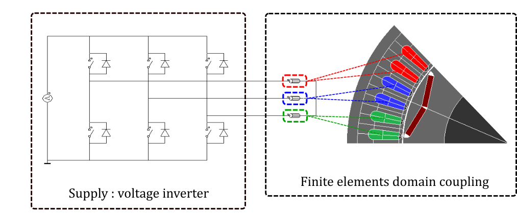
Figure 1. A Flux 2D project modeling a single pole of a 3-phase rotating electrical machine driven by a voltage inverter. The phase windings (displayed in red, blue, and green) are represented by meshed coil regions of the Coil Conductor type. The voltage inverter is represented by an external circuit coupled to the physical regions through three FE coupling components.
Given the importance of the different coil entities in Flux, further information on them is provided in the next two sections.
Meshed coils and non-meshed coils in Flux
In Flux 2D and 3D, a meshed coil region is a generic term designating collectively two types of physical regions, namely solid conductor regions and coil conductor regions (without losses, with losses and simplified geometrical description and with losses and detailed geometrical description).
Solid conductor regions are well adapted to the modeling of individual conductors with arbitrary cross-section shapes. An example is provided in Figure 2, in which an induction heating coil was modeled with the help of a solid conductor region in a coupled Steady State AC Magnetic - Transient Thermal application in Flux 3D.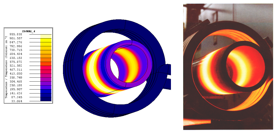
Figure 2. A coupled Steady State AC Magnetic - Transient Thermal application in Flux 3D modeling an induction heating coil with the help of solid conductor regions.
Coil conductor regions (without losses, with losses and simplified geometrical description and with losses and detailed geometrical description), on the other hand, are well suited to represent windings composed by a large number of turns of a wire with a relatively small cross-section. Consequently, they are generally assigned to faces (in Flux 2D) or volumes (in Flux 3D) representing slots or compartments enclosing the coil turns. Moreover, coil conductor regions manage all relevant parameters describing the winding configuration inside their enclosure, such as the number of turns, the wire cross-section, the fill factor, and the spacing between turns. The rotating electric machine in Figure 1 illustrates the use of three coil conductor regions to model a stator winding in Flux 2D.
From a finite element method point of view, the face or volume assigned to a meshed coil region belongs to the computational domain and is discretized by finite elements. In consequence, it is possible to evaluate and display local quantities such as the current density, the magnetic induction, and the power loss density inside these regions after completing the solution of a computation scenario.
In 3D applications, however, the description of a coil with an arbitrary shape through a meshed coil region may become too complicated, and meshing the associated volume may lead to an excessively large numerical problem. Therefore, Flux provides the user with an alternate way of specifying a coil in 3D: the non-meshed coil magnetic source.
This variety of magnetic source is an entity superposed to the 3D domain and independent from any meshed surface or volume region. In a project containing a non-meshed coil, Flux 3D evaluates the magnetic induction that it generates analytically with the Biot-Savart law. Moreover, the finite element formulation implemented in the software takes this additional field contribution into account in the meshed parts of the domain.
However, and in contrast with the case of meshed coil regions, post-processing local quantities inside a non-meshed coil is impossible. The application example in Figure 3 shows a large power transformer modeled in Flux 3D with the help of non-meshed coils and illustrates this trade-off. Given the complexity of the transformer geometry, the adoption of non-meshed coils to represent its windings results in a more straight-forward model description, but eliminates the possibility of evaluating local quanties in the transformer winding such as the current density or the temperature.
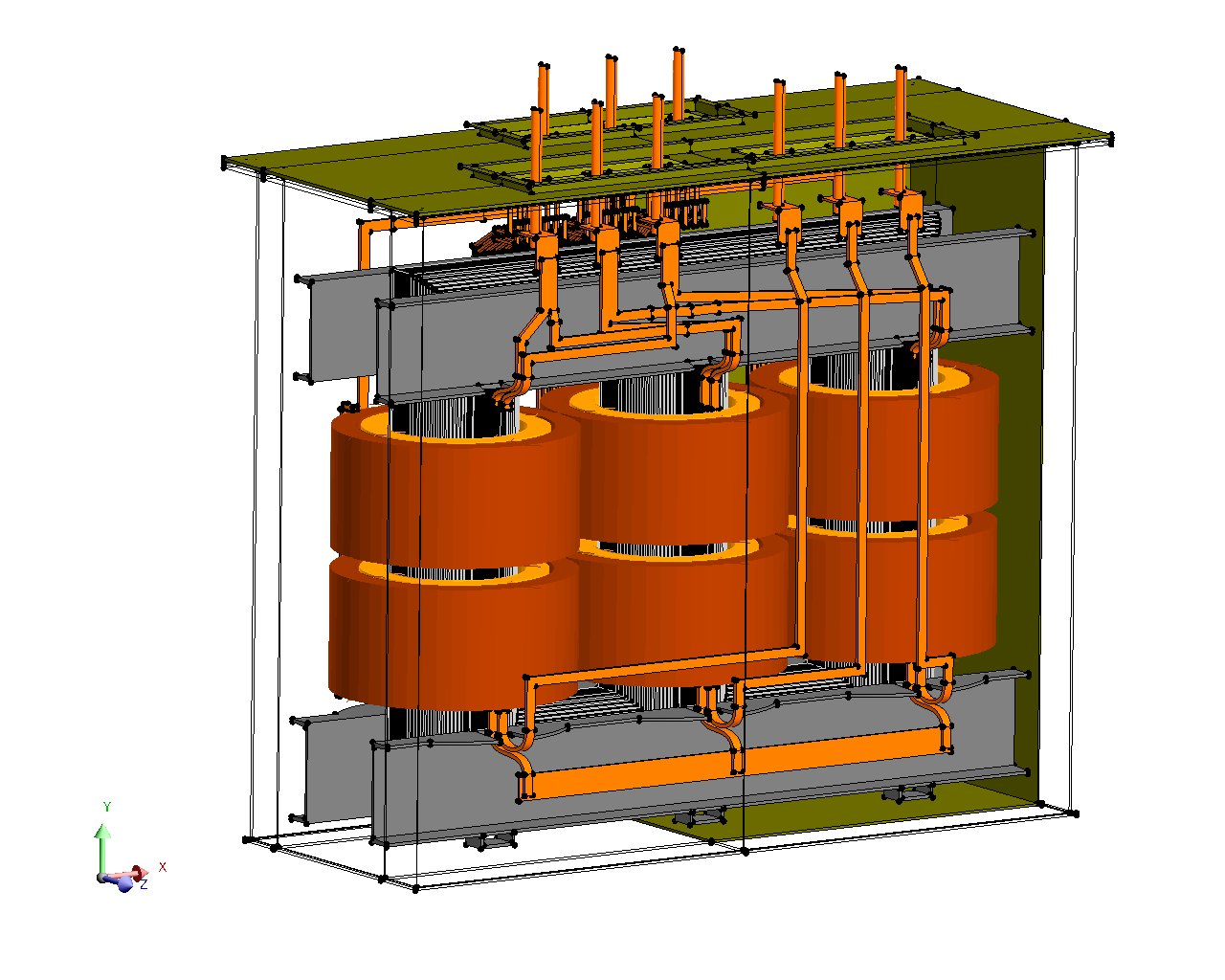
Figure 3. A power transformer modeled in Flux 3D, using non-meshed coil magnetic sources to represent its windings.
Several predefined templates of non-meshed coils are conveniently available for the user, with geometries ranging from simple circular coils to elaborated multi-saddle coils. A composed coil type exists as well, allowing the user to create a 3D non-meshed coil of arbitrary shape.
For an extended discussion on the use of meshed and non-meshed coils in Flux projects, please refer to the documentation topics below:
Finite Element (FE) Coupling Components in Flux
Finite Element (FE) coupling components are entities that could be interpreted as the lumped circuit representations of coils in a project, either in Flux 2D, Flux Skew or in Flux 3D. They provide the interfaces between meshed coil regions or non-meshed coil magnetic sources to an external circuit. As such, they are mandatory inputs required during their creation.
In some situations, the user has to assign a single FE coupling component to two distinct meshed coil regions. These are notably the cases of coils in 2D projects without physical symmetries. Under such circumstances, the first meshed coil region typically corresponds to the side of the coil injecting current in the domain, and another one represents the coil side absorbing current leaving the 2D plane. In Flux 3D, on the other hand, meshed coil regions are assigned to volumes and receive an explicit orientation for the current. As a consequence, in Flux 3D, there is a one-to-one correspondence between a FE coupling component and a single meshed coil region.
Flux provides the user with a Circuit Editor context that simplifies the tasks of creating and editing electrical networks coupled to the FEM simulation. In this environment, the user can create and treat FE coupling components as if they were conventional passive lumped circuit components and connect them in a coherent network. This procedure is performed by dragging and dropping the components and by routing the circuits tracks, in an environment resembling other circuit schematic editors, such as SPICE.
- connect the FE coupling component to an electrical circuit in the circuit editor or
- supply the coil in "imposed current" mode with an imposed value or a formula.
Moreover, three subtypes of FE coupling components are available in Flux:
- Coil conductor components: used to feed both coil conductor regions (in Flux 2D, Flux Skew and Flux 3D) and non-meshed coil magnetic sources (only in Flux 3D) with an electrical current.
- 2-terminal solid conductor components: analogous to Coil conductor components but used instead to feed solid conductor regions with 2 electrical terminals (in Flux 2D, Flux Skew and Flux 3D).
- N-terminals Solid conductor components: a subtype that is similar to the 2-terminal solid conductor component and that is required to feed solid conductor regions with more than two terminals (available only in Flux 3D). Solid conductor regions with three or more terminals are not commonly used to represent coils and windings and the same applies to the associated N-terminals solid conductor component. However, both entities may be required in specific contexts for devices with special winding topologies (e.g., autotransformers and multi-tap transformers).
Bibliographical references
For further reading on the skin and proximity effects, on the evaluation of losses in coils and on homogenization techniques, a list of bibliographical references is available here.