Presentation of working environment
Flux window
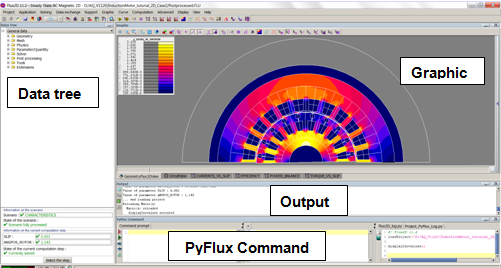
The general Flux window consists of several zones. These zones are identified in the figure below.
Configuration of the window
Flux desktop is automatically configured depending on:
- dimension of the application (2D or 3D)
- the physical application defined (no physics defined, magnetostatics, electrostatics…)
- the context: Geometry / Mesh / Physics / Solver / Post-processing (toolbars)
- or sub context (healing context for the CAD geometry…)
Role of zones
The zones and their principal roles are briefly described below:
| Element | GUI | Function |
|---|---|---|
| Title bar |  |
General information:
|
| Menus bar | Access to the different menus: Project, Application, Geometry, Mesh, Physics |
|
| Access to the different menus: Parameter/Quantity, Solving process, Post-processing |
||
| Access to the different menus: Display, View, Select, Tools, Extensions, Help |
||
| Context icons |
Access to the toolbars corresponding to the context Geometry |
|
|
Access to the toolbars corresponding to the context Mesh |
||
|
Access to the toolbars corresponding to the context Physics |
||
|
Access to the toolbars corresponding to the context Solving |
| Element | GUI | Function |
|---|---|---|
| Project Menus Toolbars | Commands of the Project menu: New, Open a project |
|
| Commands of the Project menu: Execute a command file, Save, Close, Exit |
||
| Tools Menus Toolbars | Commands of the Tools menu: Undo, Close all open dialog boxes |
| Element | GUI | Function |
|---|---|---|
| Geometry Context toolbars | Commands of the Geometry context: | |
|
||
|
||
|
||
|
||
|
||
|
||
| Mesh Context toolbars | Commands of the Mesh context: | |
|
|
|
|
|
|
|
|
|
|
|
|
|
|
|
|
|
|
|
|
|
|
|
|
| Physics context toolbars | Commands of Physics context: | |
|
|
|
|
|
|
|
|
|
|
|
|
|
|
|
|
| Solving process context toolbars | Commands of Solving process context: | |
|
|
|
|
|
|
|
|
|
|
|
|
|
|
|
|
| Post-processing context toolbars* | Commands of Post-processing context: | |
|
|
|
|
|
|
|
|
|
|
|
|
|
|
|
|
|
|
|
|
|
|
|
* only for a solved problem
| Element | GUI | Function |
|---|---|---|
| Menus Toolbars for the View | Commands of the View menu: | |
|
||
|
||
|
||
| Display | Commands of the Display menu: | |
|
||
|
||
|
||
|
||
|
||
| Selection | Commands of the Select menu: | |
|
||
|
||
|
||
|
| Element | GUI | Function |
|---|---|---|
| Data tree | 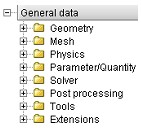 |
Entities tree of the Flux project |
| Graphic | 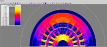 |
Geometric representation of the studied device and graphic results (isovalues, curves, arrows…) |
| Output | 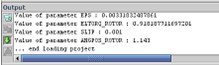 |
Informations concernant les différentes actions en cours (déroulement du programme) :
|
| Commande PyFlux |  |
Accès au nouvel éditeur python et à la mémoire des actions réalisées dans le projet |
* These zones are masked by default.
To display these zones, see Modifying the environment.