Coordinate system: about
Principle of use
The coordinate systems are used to simplify the geometry description and the movement of the devices parts.
Types of coordinate systems
The types of coordinate systems for Flux PEEC and its associated coordinates are presented below.
|
3D cartesian coordinate system Coordinates (x,y,z) |
3D cylindrical coordinate system Coordinates (r,θ,z) |
3D spherical coordinate system Coordinates (r,θ,φ) |
|---|---|---|
 |
 |
 |
Reference coordinate systems
It is possible to distinguish the following coordinate systems:
- The global coordinate system is the coordinate system in which are performed the computations. It is inaccessible for the user. The global coordinate system is a universal cartesian coordinate system using meter as length unit and degree as angle unit.
- The working coordinate systems are coordinate systems created by the user to cover
the study needs.
The working coordinate systems are defined:
- with respect to the Global coordinate system, when they refer to the global coordinate system,
- with respect to a Local coordinate system, when they refer to other coordinate systems.
All the entities are defined in the working coordinate systems (user's coordinate systems) and are evaluated in the global coordinate system for calculations.
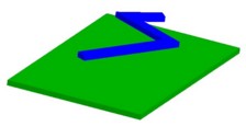
Example
To describe the device represented in the figure below, two geometric coordinate systems are used:
- A coordinate system for the description of the ground plane CART_PLAN:
Type: Cartesian
Reference coordinate system: Global
Specific characteristics:- length unit: millimeter
- angle unit: degree
Positioning:- center: 0, 0, 0
- rotation: 0, 0, 0
- A coordinate system for the description of the conductor CART_COND:
Type: Cartesian
Reference coordinate system: Local
Specific characteristics:- Parent coordinate system: CART_ PLAN
Positioning:
- center: 3, 15, 5
- rotation: -30, 0, 0
Positioning the coordinate system in its reference coordinate system
A coordinate system is positioned in its reference coordinate system using:
- the coordinates of the coordinate system center in its reference coordinate system
- the rotation angles of the axes of this coordinate system with respect to the axes of its reference coordinate system
If unfortunately your coordinate system is not defined in this way (actions performed in a different order, or rotation axis always considered with respect to the global coordinate system) you will have to re-decompose the rotations.
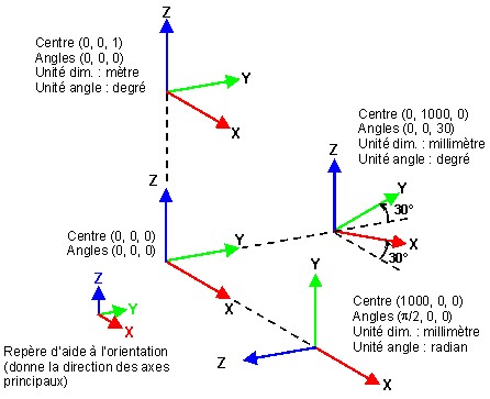
Examples of positioning
Coordinate system units
The user can define the length and angle units for a coordinate system defined with respect to the global coordinate system.
A coordinate system defined with respect to the local coordinate system inherits the units of the reference coordinate system (parent coordinate system).
Parameter setting
The origin of coordinate system and the rotation angles about axes can be defined using algebraic expression.
The algebraic expression can contain:
- constants
- geometric parameters (created beforehand)
- basic mathematical functions using operators: +, -, *, /, ( )
- usual mathematical functions admitted by FORTRAN
The mathematical functions are described in section Functions.