Trace on a Tryout Analysis
Choose points, lines, or edges to measure how the forming process changes the blank. Tracers are useful to determine the best sized blank and understand how the material flows during the forming process.
-
To see the path of a trace on the part, click
 in the Analysis Explorer.
-
Make the selection on the part, then press
 on the Animation toolbar
to view how the selected points/lines/edges move in space over time.
on the Animation toolbar
to view how the selected points/lines/edges move in space over time.
- Optional:
Click
 to
define the orientation of a line projection.
Choose from
to
define the orientation of a line projection.
Choose from- Local blank normal (default) Project the line onto the blank based on the local normal of the sheet. Varies with location.
- Draw direction Use the draw direction of the current stage to project the line onto the sheet.
- Line normal Use the normal of the plane that contains the line.
Tip:
- Tracers are associated with part features. The tracer may be deleted if changes are made to the part feature or geometry associated with it.
- Tracers can be hidden or shown by clicking their icons in the Model browser or by using the context menu.
- You can change the color and line thickness of the tracer and its trace path in the Property Editor.
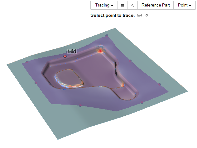
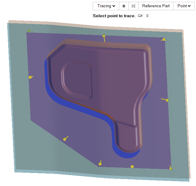
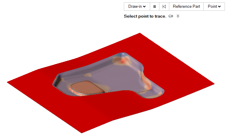
Trace Points on a Blank Without a Reference Part
-
In the Analysis Explorer, select
Tracer
.
-
Left-click as many points on the blank as you'd like to see traced.
-
Click the play button to animate the results.
Notice the traced lines projected from the blank as it is formed, marking how
the points on the blank move in space over time.
 Note: Right-click on any of the lines to reveal a context menu to further analyze the traced points. You can create Polylines and Splines, export and isolate a trail, change the color of the trail, show properties, etc.
 -
Click the Trace Results icon
 to modify the color of the traced
points, their thickness, and enable trail if desired.
to modify the color of the traced
points, their thickness, and enable trail if desired.
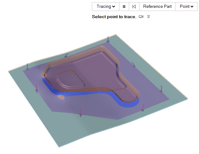
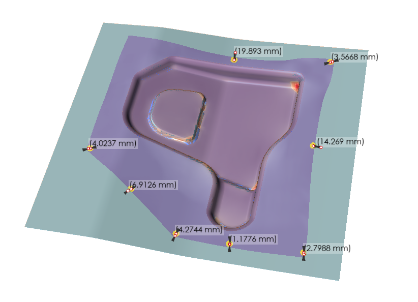
Trace Points on a Blank Using a Reference Part
Note: This tracer is created using a reference part, so it can not be extended to other
operations.
-
In the Analysis Explorer, select
Tracer
.
-
Click Reference Part and select the reference
part.

-
Left-click as many points on the blank that you'd like to see traced in
relation to the reference part.
-
Click the play button to animate the results.
Notice the traced lines projected from the blank as it is formed, marking how
the points on the blank move on the Reference Part over
time along the draw direction.
Note: Right-click on any of the lines to reveal a context menu to further analyze the traced points. You can create Polylines and Splines, export and isolate a trail, change the color of the trail, show properties, etc. -
Click the Trace Results icon to modify the color of the traced
points, their thickness, and enable trail if desired.
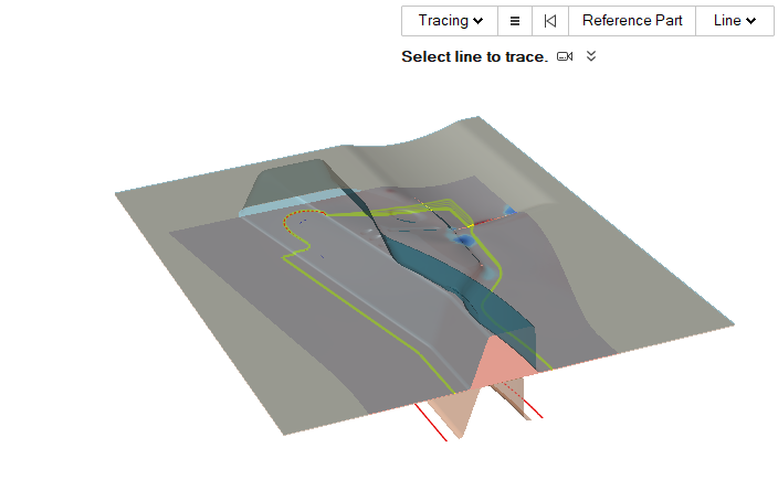
Trace Lines on a Blank Without a Reference Part
-
In the Analysis Explorer, select
Tracer
.
-
Select a line to trace.
-
Click the play button to animate the results. Notice the traced lines
projected from the blank as it is formed, marking how the line on the blank move
in space over time.
-
Click the Trace Results icon to modify the color of the traced
points, their thickness, and enable trail if desired.
 Note: Right-click on any of the lines to reveal a context menu to further analyze the traced points. You can create Polylines and Splines, export and isolate a trail, change the color of the trail, show properties, etc.
 -
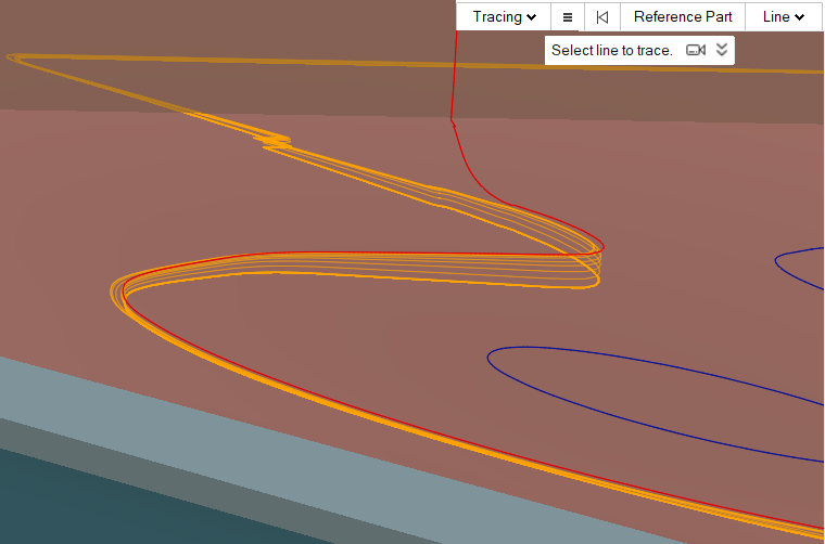
Zoom in on a traced line to analyze it further.
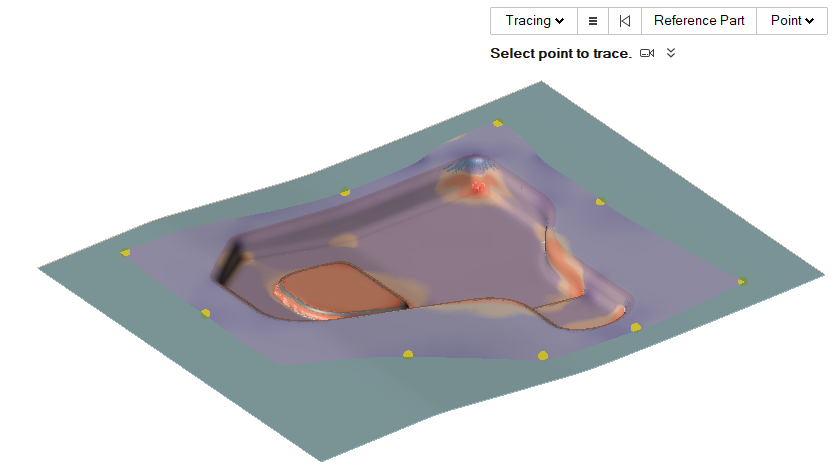
Trace Material Draw-In On a Sheet
Note: This tracer is created using a reference part, so it can not be extended to other
operations.
-
In the Analysis Explorer, select
Tracer
.
-
Click Reference Part and select the reference
part.
-
Left-click as many points on the blank that you'd like to see traced in
relation to the reference part.

-
Click the play button to animate the results.
Notice the traced lines projected from the blank as it is formed, marking how
the points on the blank move on the Reference Part over
time along the draw direction.
Note: Right-click on any of the lines to reveal a context menu to further analyze the traced points. You can create Polylines and Splines, export and isolate a trail, change the color of the trail, show properties, etc. -
Click the Trace Results icon to modify the color of the traced
points, their thickness, and enable trail if desired.
Create Geometry from a Trace Path
- Create a tracer and run a motion analysis.
- Right-click on the tracer and select Create Spline from the context menu. A massless part is created in the Model Browser. This part can now be pushed, pulled, and otherwise manipulated.
Note:
- To create valid splines, make sure the trace path does not loop back over itself. Try reducing the End Time to control how far the trace path extends.
- Alternatively, you can create a polyline by selecting Create Polyline from the context menu. Polylines are segmented rather than smooth line spline curves.
- Multiple selection is supported if you have multiple trace paths that you want to convert to splines or polylines.
- If you want to keep a tracer for future use, ground the spline that you created or add it to a rigid group.
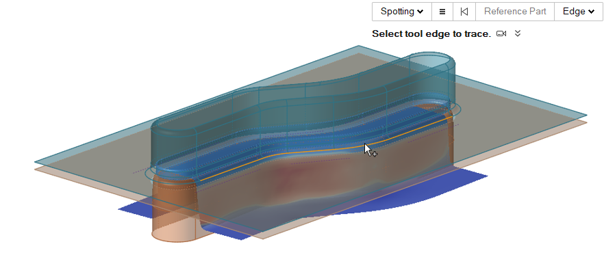
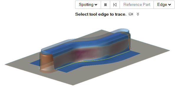
Spot Tool Edge on a Blank
Note: This tracer is created by selecting a tool edge of an operation, so it can not
be extended to other operations.
-
In the Analysis Explorer, select
Tracer
.
-
Select a tool edge to be spotted on the blank during forming.
The tools are displayed at the start position.
-
Click the play button
to animate the results. Notice the selected edge is projected onto the blank at
every step where it touches the blank and is shown for the current step.
-
Click the Trace Results icon to modify the color of the traced
points, their thickness, and enable trail if desired.
Note:
- Right-click on any of the lines to reveal a context menu to further analyze the traced points. You can create Polylines and Splines, export and isolate a trail, change the color of the trail, show properties, etc.
- Joined lines are selected automatically. To select individual segments, press Ctrl and click those segments.
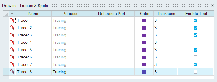
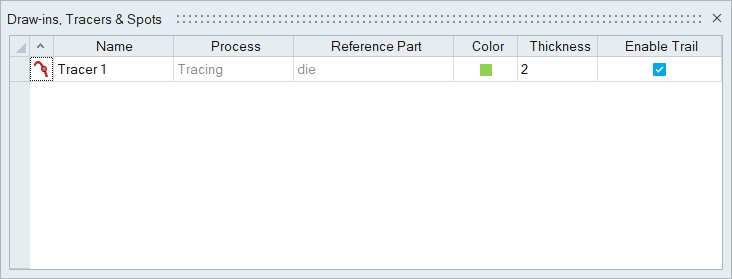
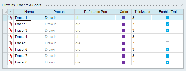
Tracers Table
The Tracers Table lists all of the tracers in your model and allows you to edit various attributes.
Location: Tracers tool, satellite icon ![]()
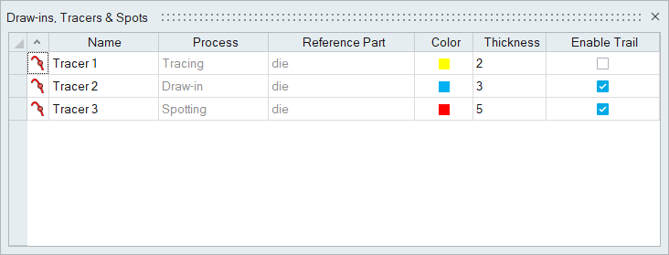
Figure 1. Tracers Table
| To | Do this |
|---|---|
| Rename a tracer | Select the cell in the table and then click again to make the field editable. |
| Change the color | Select the color cell in the table and then select a different option from the color palette. |
| Sort a column | Click the column header. Click repeatedly to toggle between ascending and descending order. |
| Add or remove columns | Right-click on a column header. |
Shortcuts
| To | Do this |
|---|---|
| Select a reference part | While a tracer is selected, hold down the Ctrl key and left-click a part to act as the paper. |
| Exit the tool | Right-click and mouse through the check mark to exit, or double-right-click. |