|
»Click here to display Table of Contents«
|

Scale panel |

|

|

|

|
|
Scale panel |
|
|

|

|
|
»Click here to display Table of Contents«
|
Scale panel |
|
|
|
|
|
Scale panel |
|
|
|
|
Use the Scale panel to increase or decrease an entity’s dimensions. Scaling can be proportional or non-proportional.
Notes
|
There are no subpanels on the Scale panel. All inputs and command buttons are located on the main panel.
Input |
Action |
||||||
entity selector |
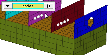
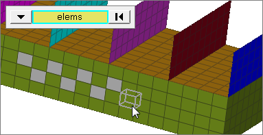
Used to select entities for scaling. Valid entity types include nodes, elements, components, lines, surfaces, groups, points, blocks, solids, and connectors. When you select nodes or elems, click the switch to change the selection mode.
|
||||||
origin |
Entities scale based on their position relative to an origin node. Click node twice to type in a node id, or click once and then click in the graphics area to set the origin node. |
||||||
coordinate system |
Choose between coordinate system types. Use global system to scale entities relative to the global coordinate system; Use local system to scale entities relative to a specific local coordinate system.
|
||||||
x scale = |
Type in the factor by which the selection will scale in the selected system’s x direction. See the notes below for more details. |
||||||
y scale = |
Type in the factor by which the selection will scale in the selected system’s y direction. See the notes below for more details. |
||||||
z scale = |
Type in the factor by which the selection will scale in the selected system’s z direction. See the notes below for more details. |
||||||
face angle / individual selection |
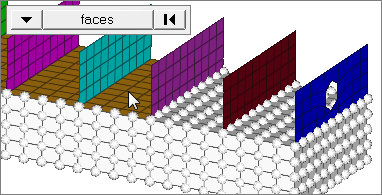
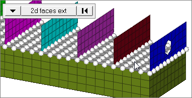
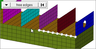
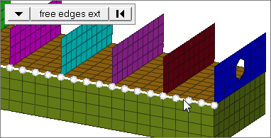
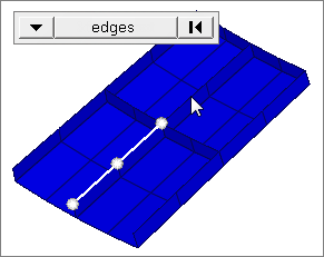
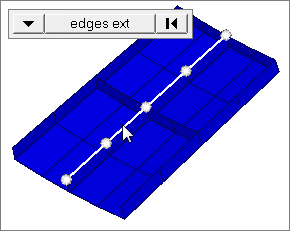
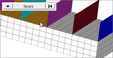
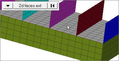
Face angleThe face angle is the angle between the normal of facets that share an element edge. A facet can either be a shell element itself, or one of the faces of a solid element. The normal of triangular facets is that of the plane defined three corner vertices. Whereas, the normal of quadrilateral facets is calculated by taking the cross-product between its two diagonals. This special treatment for quadrilaterals is because a warped shape does not lie completely on a plane. Only available when the entity selector is set to nodes or elems and the selection mode is set to faces, 2d faces ext, free edges, free edges ext, edges, or edges ext.
Individual SelectionSelect individual elements on a face or select individual free/shared edges of elements. Only available when the entity selector is set to nodes or elems and the selection mode is set to faces, free edges, or edges. |
||||||
edge angle |
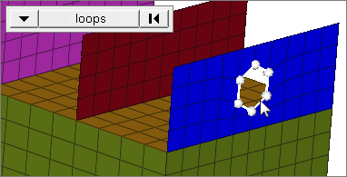
Splits edges that belong to a given face. When the edge angle is 180 degrees, edges are the continuous boundaries of faces. For smaller values, these same boundary edges are split wherever the angle between segments exceeds the specified value. A segment is the edge of a single element. Only available when the entity selector is set to nodes and the selection mode is set to free edges, free edges ext, edges, or edges ext. |
The following action buttons appear:
Button |
Action |
uniform |
Click this button to open a text box, then type the desired scaling factor. The x scale, y scale, and z scale fields automatically change to this value so that the scaling is proportional. |
scale+ |
Increases the selection’s dimensions relative to the coordinate system and origin chosen. The scaling factor acts as a multiplier — so, for example, a factor of 2 doubles the selection’s dimensions. |
scale- |
Decreases the selection’s dimensions relative to the coordinate system and origin chosen. The scaling factor acts as a divisor — so, for example, a factor of 2 halves the selection’s dimensions. |
return |
Finalizes the current scaling and exits the panel. |