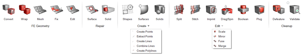
Geometry

Create, edit, and cleanup geometry.

Attention: The icons shown on the ribbon below are used to complete this workflow. Click an icon to learn more about the tool.
Use the Convert tool to tessellate b-spline geometry and convert to discrete geometry. In CFD modeling, input parts can have topology issues, like free surfaces and self-intersections, and part assembly issues, such as parts with very close proximity and intersecting parts. Manually connecting these parts can be time consuming and require expertise in certain tools. The Wrap tool can generate a watertight manifold model from dirty input with considerably less manual work. Use the Mesh to create new surface mesh on converted geometry. Use the Fix tool to improve the quality of an FE (discrete/mesh) model. Use the Edit tools to manually improve the quality of surface mesh elements and nodes. Use the Surface tool to find, review, and fix any geometric errors in the model's surfaces. Use the Solid tool to find, review, and fix any geometric errors in the model's solids. Create and edit circles and rectangles with the Shapes tool. A surface represents the geometry associated with a physical part. A surface is a two-dimensional geometric entity that may be used in automatic mesh generation. Solids are closed volume of surfaces that can take any shape. Solids are three-dimensional entities that can be used in automatic tetra and solid meshing. Use the Create Points/Nodes tool to create and edit points/nodes on geometry surfaces and lines or in space. Points and nodes can be used to establish reference locations for geometry construction and meaningful snap locations for use with other tools. Use the Extract Points/Nodes tool to interpolate and divide an edge or line, and find the center of an arc, fillet, or multiple curve segments. Use the Create Lines tool to draw free lines for geometry construction and to generate meaningful snap locations to be used by other tools. Use the Combine Lines tool to create a new continuous line segment between two existing lines, resulting in a single seamless line. Use the Create Polylines tool to draw polylines for geometry construction and to generate meaningful snap locations to be used by other tools. Use the Split tools to create fixed points and split surfaces or solids using a variety of methods. Use the Stitch tool to stitch and unstitch adjacent or overlapping surfaces, and suppress or unsuppress edges. Use the Imprint tool to imprint geometry onto target surfaces or lines, thus creating new fixed points or edges. Use the Drag/Spin tool to push or pull surfaces and spin lines and surfaces in order to creates surfaces or solids. Use the Boolean tool to combine solids, subtract one solid from another, and find the intersection out of the solids. Use the Plug tool to find and fill cavities. The Plug tool can also be used to remove protrusions, holes, and complex features. Use the Scale tool to resize geometry in your model. Use the Mirror tool to mirror/reflect selected entities across a symmetry plane. Use the Fuse tool to connect discrete topology surfaces/solids/parts. The Fuse tool can be utilized to connect close proximity inputs by defining a threshold. Merge two or more solids or surfaces. Solids are merged by removing shared faces while surfaces are merged by suppressing shared edges. Use the Defeature tool to automatically find, review, and defeature holes and other non-essential features. Use the Validate tool to validate your entire model, review surface and solid checks, and fix any issues.