OS-E: 0705 Periodic Boundary Conditions
Periodic Boundary Conditions via PERBC can be used to match results from one part of the structure to another. This allows using a truncated model to reduce runtime if there is sufficient symmetry in the original model.
RELOC entry is used to provide mapping for grids that require to me matched on both sides of the truncated structure.
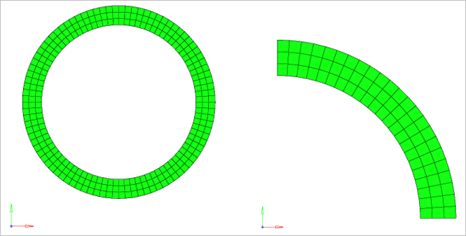
Figure 1. Original Full Ring (symmetric) and Truncated Model (quarter ring)
Model Files
Refer to Access the Model Files to download the required model file(s).
The model files used in this example include:
- ring_new_complete.fem
- ring_truncated_perbc.fem
Model Description
- FE Model
- 2D Elements
- CQUAD4
- MAT1
- Young’s Modulus
- 2.1E5
- Poisson's Ratio
- 0.3
PERBC entry is used to match results from one side to another. RELOC is used to only provide the mapping for the grids that need to be matched on both sides of the truncated structure.
If RELOC(ROTATE) is specified, then all matching grids on both sides of the truncated structure should have a cylindrical coordinate system assigned with the Z-axis matching the axis used for RELOC rotation. The origin of the cylindrical system should coincide with the center of the ring.
In the current example, a grid set for one end of the truncated ring is created. This grid set is referenced on the GSID field of the PERBC entry. A corresponding tolerance is specified via the TOL field depending on model quality. A RELOC entry is defined purely to map the locations of the grids from one end to the other.
The TYPE field is set to ROTATE since we are mapping based on rotation. The GID1 on RELOC entry references the center of the ring (which is also the center of the local cylindrical system).
The ang_x and ang_y fields are set to 0.0 and ang_z is set to 90.0 on the RELOC entry.
The RELOC entry should be referenced on the PERBC entry on the RLID field.
If the mesh is symmetric and the rotation angle is correctly specified, then RELOC will accurately find the grids at the other end of the truncated ring.
Full model loading on the grids at the corners of the truncated ring are proportionally reduced (typically halved for shells) since the force that was initially applied on multiple elements is being applied to one.
Results
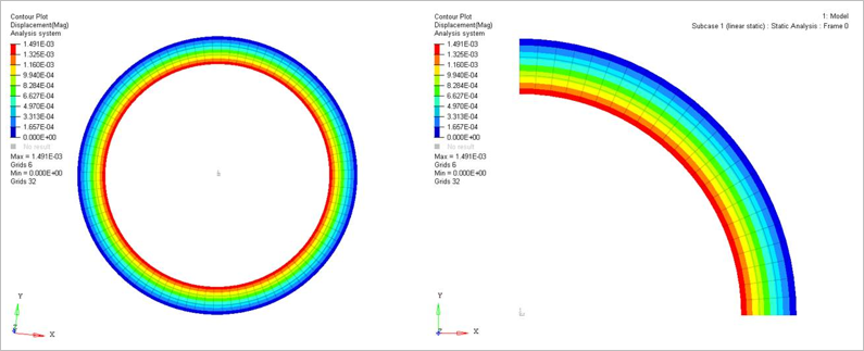
Figure 2. Results of Full Model and Truncated Model are Identical