Ignore Edges
In some cases, the geometry designed for a case (such as an urban scenario case) features a plane that is used as a ground plane for the simulation. This plane is always a plane with finite dimensions and therefore the edges of the plane are taken into account when calculating reflected and diffracted rays using the GTD approach.
The "Ignore Edges" menu option under the "Meshing" menu allows the user to ignore specific edges of the geometry, so that these edges are not taken into account when performing the ray-tracing. In the example specified before, this option would allow a user to ignore the edges of the ground plane, so that this ground plane would behave like an infinite ground plane.
In order to specify the edges to be ignored, the user needs to select the "Ignore Edges" under the "Meshing" menu:
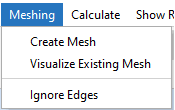
Figure 1. "Ignore Edges" menu option
The following panel will appear when this option is selected. Note that it may take a few seconds to detect all the edges in the geometry.
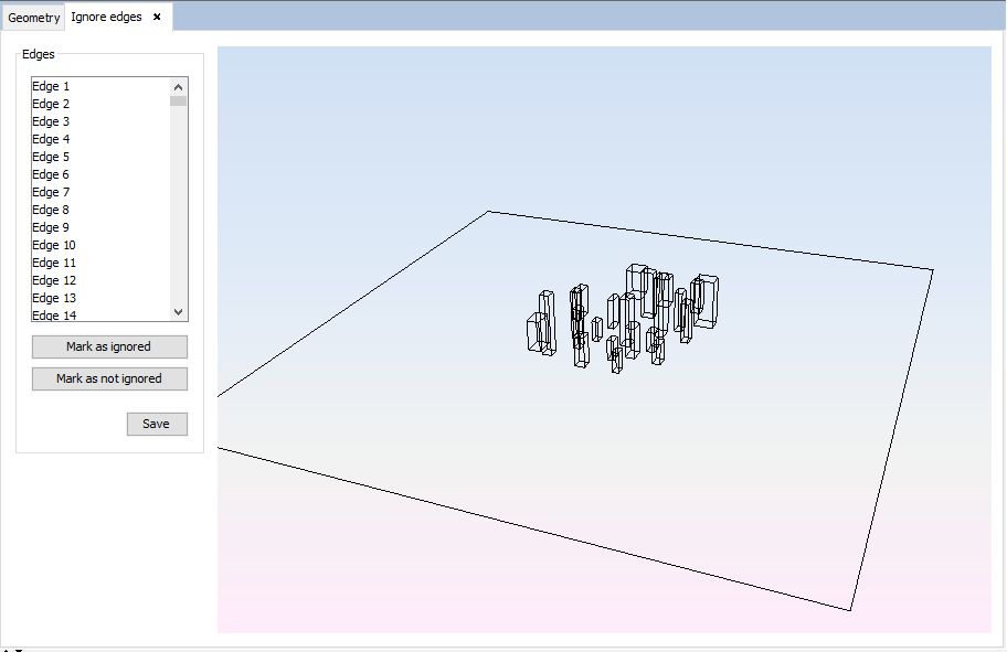
Figure 2. "Ignore Edges" panel
It is possible to select the edges to be removed by clicking on them in the geometry panel (holding the Ctrl key allows selection of many edges at once). It is also possible to select the edges on the list at the left side of the panel. When an edge is selected, it is drawn as a thicker yellow-colored line. The "Mark as ignored" button allows the user to ignore the currently selected edges. The ignored edges will be drawn as a dashed line in the geometry view, as shown in the following figure:
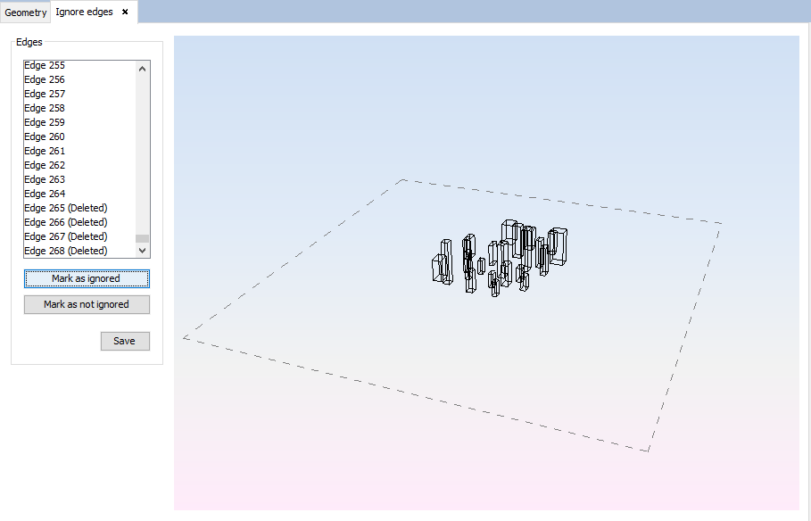
Figure 3. "Ignore Edges" panel, showing some ignored edges
In order to undo the "Mark as ignored" operation, the user needs to select the currently ignored edges and then press the "Mark as not ignored" button.
When the user has finished marking edges as ignored, they need to press the "Save" button to save the changes. The ignored edges will not be taken into account in subsequent simulations.