Parameters
When the user selects the "Parameters" option under the "Simulation" menu, the following panel will appear:
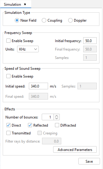
Figure 1. Simulation parameters panel
This panel allows the user to select the simulation type for the current case. The "Near Field" simulation type consists on the computation of the sound pressure field in a set of points known as "observation points". The "Coupling" simulation type allows the calculation of coupling values between a set of sources and a passive receptor. The "Doppler" simulation type takes into account the relative speed and rotation of objects, observation points and sources to calculate the Doppler Shift.
The "Frequency Sweep" panel allows the configuration of the frequency of sound waves considered for the simulation. There are two possibilities:
- Single frequency When the "Enable Sweep" check box is unchecked, the results will be computed only for the frequency specified in the "Initial frequency" field.
- Frequency sweep When the "Enable Sweep" check box is checked, the results will be computed for a set of frequencies bounded by the specified values in the "Initial frequency" and "Final frequency" fields. The number of frequencies used for the frequency sweep is given in the "Samples" field. The sampled frequencies in the frequency sweep will be evenly-spaced.
The "Speed of Sound Sweep" panel allows the configuration of the speed of the sound waves in the simulation. As with the frequency, there are two options. If the "Enable Sweep" check box is unchecked, only the speed given in the "Initial speed" will be used in the simulation. Otherwise, the user can specify a range of speeds to compute the results for, as well as the number of samples within that range that will be used.
The sound pressure field is computed by taking into account the multiple paths the sound waves make in their way from the ultrasound source to each observation point. The "Effects" panel allows the user to set up which effects are considered when computing these paths. The available options are the following:
- Number of bounces: The maximum number of bounces considered in path calculation. Paths which exceed the number of bounces specified here are not computed.
- Direct: If this option is selected, the simulation will be performed taking into account direct rays.
- Reflected: If this option is selected, the simulation will be performed taking into account reflected rays.
- Diffracted: Determines whether diffracted rays are computed.
- Creeping: Determines whether creeping rays are computed. This option isn't available at the moment.
- Transmission: Determines whether transmitted rays are computed.
The Filters rays by distance is only enabled when the coupling option is set up. It determines the minimum distance from which the rays will be considered for the coupling calculation.
The Advanced Parameters button allows the user to configure parameters that are closer to the computation algorithm. When the user presses this button, the following dialog will appear:
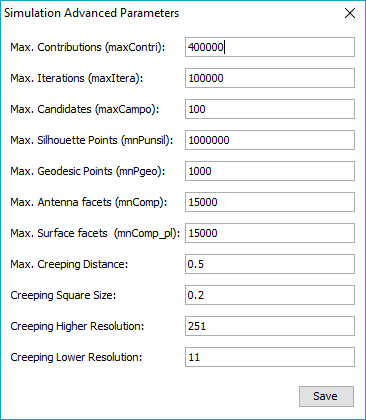
Figure 2. Simulation advanced parameters dialog
All these parameters are detailed below:
- Max. Contributions maximum number of contributions to taken into account. A contribution is for instance that due to a given double ray-path.
- Max. Iterations maximum number of contributions that are taken into account.
- Max. Candidates maximum number of surfaces that can shadow other surfaces.
- Max. Silhoutte Points maximum number of points for the silhoutte when creeping wave paths are computed.
- Max. Geodesic Points maximum number of geodesic points when computed a creeping wave path.
- Max Antenna facets maximum number of facets to be stored in the anxel of Z-Buffer matrix of the source.
- maximum number of facets to be stored in the anxel of Z-Buffer matrix of every surface.
- Max Creeping Distance maximum distance between a surface and the antenna to increase the creeping sample resolution.
- Creeping Square Size size edge of the square where the creeping sample resolution is increased near the antenna.
- Creeping Higher Resolution higher sampling resolution per surface used to compute the creeping silhoutte.
- Creeping Lower Resolution lower sampling resolution per surface used to compute the creeping silhoutte.
After setting up the simulation parameters, the user may press the Save button to save the configuration.