Advanced Modeling Guidelines
Workflow tips for advanced modeling in SimSolid.
-
Use bushings to create connectors or constraints with specific degrees of
freedom.
-
Set stiffness values to either 0 (free) or Rigid.
Note: The directions in the Stiffness tab reference the local coordinates for each bushing, not the global coordinate system. You can change the global coordinate system in the Coordinate system tab.
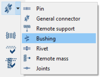
Figure 1. Connections > Virtual Connectors > Bushing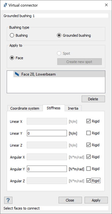
Figure 2. Grounded bushings with Linear and Angular Y DOF Free and All Others Rigid
-
Set stiffness values to either 0 (free) or Rigid.
-
Use enforced displacement to create constraints with specific degrees of
freedom.
-
Set displacement to 0 to constrain all displacement in specific
direction(s) on faces.
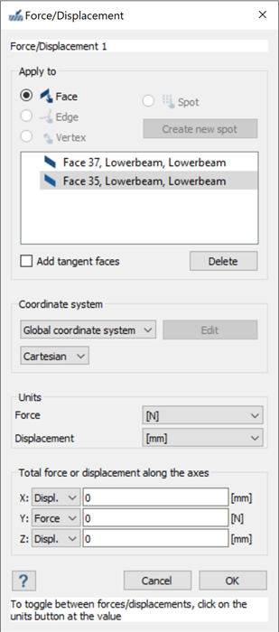 Figure 3. Force/Displacement to Constrain Displacement in X and Z
Directions, Allow Translation in Y
Figure 3. Force/Displacement to Constrain Displacement in X and Z
Directions, Allow Translation in Y
-
Set displacement to 0 to constrain all displacement in specific
direction(s) on faces.