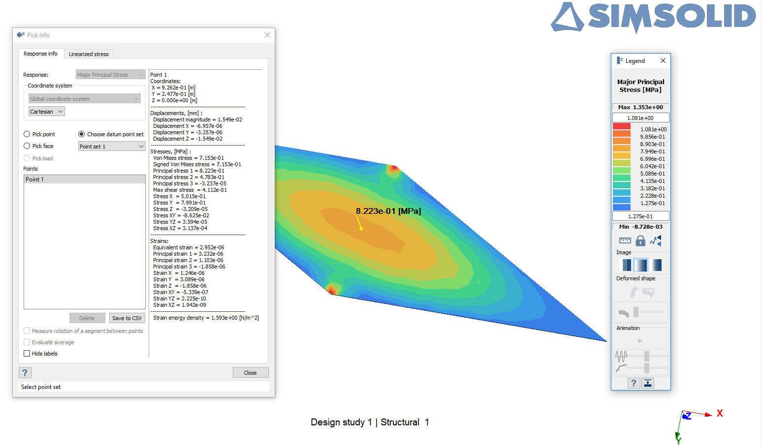
Test No. VS14Find the maximum principle stress at the
skew plate center at point E.
Definition
Figure 1.
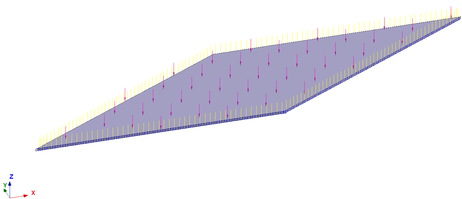
A skew plate (Figure 1) is
subjected to uniform pressure.
The load is 0.7 KPa. The plate is simply supported at the perimeter: Uz = 0 along edges AB,
BC, CD, and AD. Ux = Uy = 0 at point A and Uy = 0 at point B to prevent rigid body
motion.
The material properties are:
Properties
Value
Modulus of Elasticity
2.1e+11 Pa
Poisson's Ratio
0.3
Results
Two spot-points were created at the plate corners A and B in the mid-plane. This allows for
application of constraints which eliminate rigid in-plane translation-rotations of the plate
(Figure 2).
Figure 2.
To simulate simple supports, four spot-lines were created at the plate mid-plane around the
plate perimeter (Figure 3).Figure 3.
Vertical constraint Uz = 0 was applied to the spot-lines.
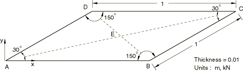

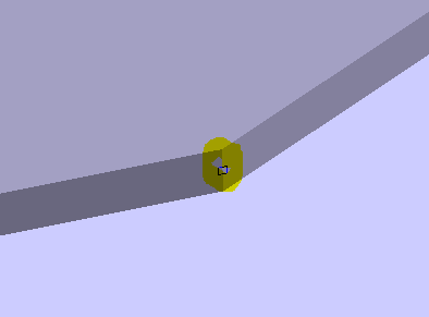
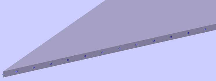 Figure 3.