SS-V: 4010 Bimetallic Cantilever Beam
Test No. VTL02Determine the displacements at the centerline at free end and bending stress at outer fiber for a bimetallic cantelever beam.
Definition
A cantilever beam is built from two equal thickness layers of different metals (Figure 1). The beam is fixed at centerline at one end (translations and rotation around the centerline are set to zero) and is subjected to uniform temperature change of 100 degrees Fahrenheit.
Both layers of materials have the same dimensions 10 x 1 x 0.05 inch.
- Properties
- Value
- Modulus of Elasticity
- 3.e+7 psi
- Poisson's Ratio
- 0
- Coefficient of thermal expansion: top layer
- 2.e-5 in/in-F
- Coefficient of thermal expansion: bottom layer
- 1.e-5 in/in-F
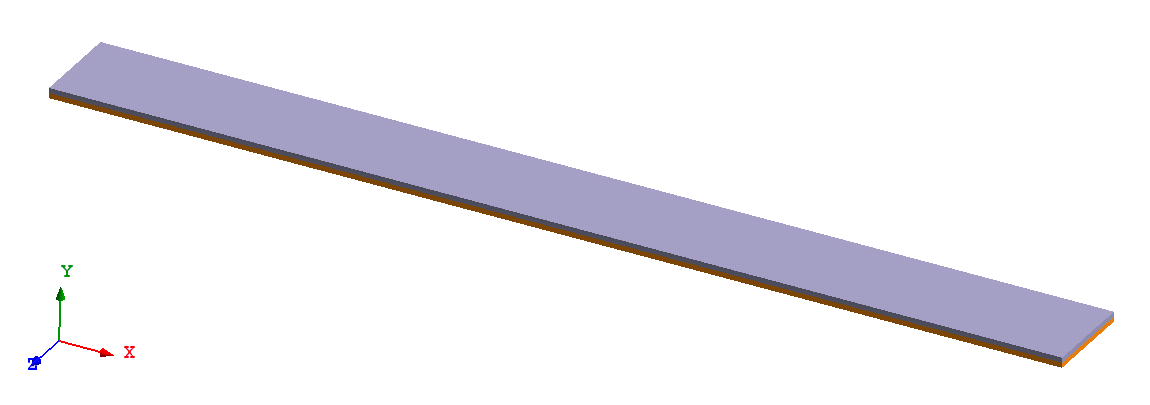
Figure 1.
Results
Layers of the beam are simulated by solids glued together. In order to reproduce as close as possible boundary conditions of beam theory used in reference, the edge at centerline at “fixed” end of the beam is constrained in lateral directions. To eliminate rotations around the edge and sliding along the edge a point at the corner of upper fiber is fixed in two directions (Figure 2).
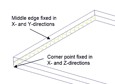
Figure 2. Constraints at ‘fixed” end
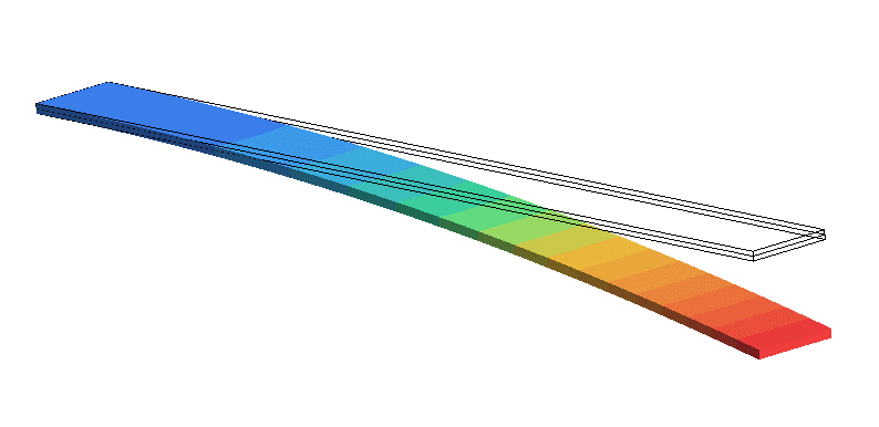
Figure 3. Beam deformation
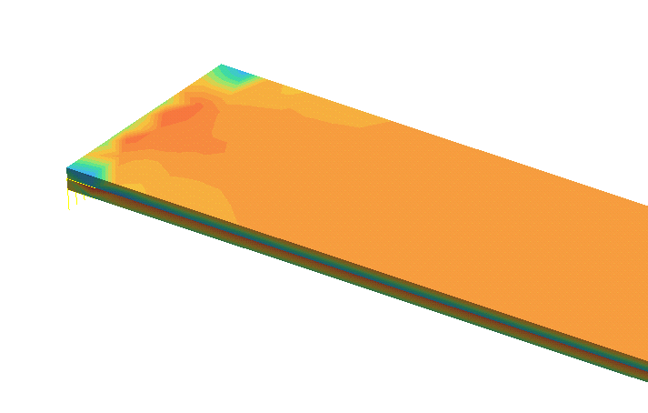
Figure 4. Distribution of bending stress X at “fixed” end
| Ref Solution | SimSolid | % Difference | |
|---|---|---|---|
| Free End, Middle Fiber, Disp X [in] | 1.5000E-02 | 1.5020E-02 | 0.13% |
| Free End, Middle Fiber, Disp Y [in] | 7.5000E-01 | 7.4950E-01 | -0.07% |
| Top Fiber, Stress [psi] | 7.5000E+03 | 7.4530E+03 | -0.63% |